
Maintenance and Service Guide
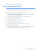
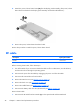
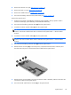
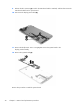
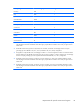
Table Of Contents

4. Remove the SIM slot cover (see SIM slot cover on page 13).
5. Remove the back cover (see
Back cover on page 14).
6. Remove the middle frame (see
Middle frame on page 16).
7. Disconnect the battery cable from the system board (see
Battery on page 19).
Remove the system board:
1. Detach the top speaker cable (1) from the display panel assembly. (The top speaker cable is
attached to the display panel assembly with double-sided adhesive.)
2. Disconnect the front-facing webcam cable (2) from the system board.
3. Unsolder the vibrator module cables (3) from the system board.
NOTE: The vibrator module red cable is soldered to the system board “+” vibrator module
terminal. The vibrator module black cable is soldered to the system board “-” vibrator module
terminal.
4. Unsolder the receiver module cables (4) from the system board.
NOTE: The receiver module red cable is soldered to the system board “+” receiver module
terminal. The receiver module black cable is soldered to the system board “-” receiver module
terminal.
5. Disconnect the front-facing webcam cable (5) from the system board.
6. Release the ZIF connector (6) to which the power/volume button board cable is attached, and
then disconnect the power/volume button board cable from the system board.
7. Release the ZIF connector (1) to which the TouchScreen cable is attached, and then disconnect the
TouchScreen cable from the system board.
8. Disconnect the RF cable from the terminal (2) on the system board.
System board
29