HP 7 VoiceTab Tablet Maintenance and Service Guide IMPORTANT! This document is intended for HP authorized service providers only.
© Copyright 2014 Hewlett-Packard Development Company, L.P. Bluetooth is a trademark owned by its proprietor and used by Hewlett-Packard Company under license. SD Logo is a trademark of its proprietor. The information contained herein is subject to change without notice. The only warranties for HP products and services are set forth in the express warranty statements accompanying such products and services. Nothing herein should be construed as constituting an additional warranty.
Safety warning notice WARNING! To reduce the possibility of heat-related injuries or of overheating the device, do not place the device directly on your lap or obstruct the device air vents. Use the device only on a hard, flat surface. Do not allow another hard surface, such as an adjoining optional printer, or a soft surface, such as pillows or rugs or clothing, to block airflow. Also, do not allow the AC adapter to contact the skin or a soft surface, such as pillows or rugs or clothing, during operation.
iv Safety warning notice
Table of contents 1 Product description ........................................................................................................... 1 2 External component identification ..................................................................................... 3 3 Illustrated parts catalog .................................................................................................... 4 Locating the part number and serial number ...............................................................
Rear-facing webcam ............................................................................................................... 24 Power/volume button board .................................................................................................... 25 RF cable ............................................................................................................................... 26 USB board ..................................................................................................
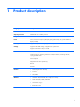
1 Product description Category Description Product Name HP 7 VoiceTab Tablet Chipset/processor MT8382 QC A7 1.30-GHz processor Graphics Mali 400 MP2 500-MHz Panel 6.95-in, transmissive liquid crystal display (LCD), (600×1024), TN, 5-point MultiTouch display assembly Memory Supports 1 GB system memory, integrated onto system board Storage Supports 8 GB eMMC storage, integrated onto system board Supports external Micro SD up to 32 GB Audio and video 0.3-MP, front-facing webcam 5.
Category Description Ports ● Micro USB type B with MHL support ● Micro SD slot ● Micro SIM slot ● Audio jack: 3.5-mm with microphone Power requirements Supports a 3000-mAh, USB-charging battery Supports a 5V-1A, USB cable AC adapter 2 Operating system Preinstalled: Android 4.4.
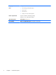
2 External component identification Item Component Item Component (1) Audio-out (headphone)/Audio-in (microphone) jack (6) Volume control buttons (2) Rear-facing webcam (7) Micro SD Card Reader slot (3) Front-facing webcam (8) Microphone (4) Speaker (9) Microphone (5) Power button (10) Micro USB port 3
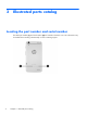
3 Illustrated parts catalog Locating the part number and serial number The tablet part number (1) and serial number (2) are located on the back cover. This information may be needed when travelling internationally or when contacting support.
Tablet major components Item Component Spare part number (1) SIM slot cover 781986-001 (2) Back cover 781978-001 (3) Middle frame (includes power/volume button actuator, shielding, and speaker gaskets) 781980-001 (4) Speaker Kit (includes left and right speakers) 781987-001 (5) Rear-facing webcam (includes cable and double-sided adhesive): 5.0-MP, auto-focus webcam 791010-001 2.
Item Component Spare part number System board with vibrator module and receiver module 787828-001 Ambient light sensor rubber gasket (not illustrated) 781985-001 (14) Display panel assembly (6.
Sequential part number listing Spare part number Description 781104-001 Battery, 3000-mAh, USB-charging (includes cable and double-sided adhesive) 781976-001 5-V/1-A AC adapter (includes plug) 781977-001 Antenna (includes double-sided adhesive) 781978-001 Back cover 781979-001 RF cable 781980-001 Middle frame (includes power/volume button actuator, shielding, and speaker gaskets) 781981-001 HP 7 VoiceTab Tablet equipped with a 6.
4 Removal and replacement preliminary requirements Tools required You will need the following tools to complete the removal and replacement procedures: ● Flat-bladed screw driver ● Magnetic screw driver ● Phillips P0 screw driver ● Phillips P00 screw driver Service considerations The following sections include some of the considerations that you must keep in mind during disassembly and assembly procedures.
Drive handling CAUTION: Drives are fragile components that must be handled with care. To prevent damage to the computer, damage to a drive, or loss of information, observe these precautions: Before removing or inserting a drive, shut down the computer. If you are unsure whether the computer is off or in Hibernation, turn the computer on, and then shut it down through the operating system. Before handling a drive, be sure that you are discharged of static electricity.
CAUTION: To prevent damage to the computer when you are removing or installing internal components, observe these precautions: Keep components in their electrostatic-safe containers until you are ready to install them. Before touching an electronic component, discharge static electricity by using the guidelines described in this section. Avoid touching pins, leads, and circuitry. Handle electronic components as little as possible. If you remove a component, place it in an electrostatic-safe container.
Packaging and transporting guidelines Follow these grounding guidelines when packaging and transporting equipment: ● To avoid hand contact, transport products in static-safe tubes, bags, or boxes. ● Protect ESD-sensitive parts and assemblies with conductive or approved containers or packaging. ● Keep ESD-sensitive parts in their containers until the parts arrive at static-free workstations. ● Place items on a grounded surface before removing items from their containers.
Equipment guidelines Grounding equipment must include either a wrist strap or a foot strap at a grounded workstation. ● When seated, wear a wrist strap connected to a grounded system. Wrist straps are flexible straps with a minimum of one megohm ±10% resistance in the ground cords. To provide proper ground, wear a strap snugly against the skin at all times. On grounded mats with banana-plug connectors, use alligator clips to connect a wrist strap.
5 Removal and replacement procedures CAUTION: Tablet components described in this chapter should only be accessed by an authorized service provider. Accessing these components can damage the tablet or void the warranty. NOTE: HP continually improves and changes product parts. For complete and current information on supported parts for the tablet/keyboard, go to http://partsurfer.hp.com, select the country or region, and then follow the on-screen instructions.
4. Remove the SIM slot cover (3). Reverse this procedure to install the SIM slot cover. Back cover Description Spare part number Back cover (includes power/volume button actuator, shielding, and speaker gaskets) 781978-001 Before removing the back cover, follow these steps: 1. Turn off the tablet. If you are unsure whether the tablet is off or in Hibernation, turn the tablet on, and then shut it down through the operating system. 2.
CAUTION: Before positioning the tablet with display panel facing down, make sure the work surface is clear of tools, screws, and any other foreign objects. Failure to follow this caution can result in damage to the display panel. 1. Position the tablet with the display panel facing down and the micro SD Card Reader slot toward you. 2. Use a case utility tool (1) or similar thin tool to separate the back cover from the middle frame. 3.
Middle frame Description Spare part number Middle frame (includes power/volume button actuator, shielding, and speaker gaskets) 781980-001 Before removing the middle frame, follow these steps: 1. Turn off the tablet. If you are unsure whether the tablet is off or in Hibernation, turn the tablet on, and then shut it down through the operating system. 2. Disconnect the power from the tablet by unplugging the power cord from the tablet. 3. Disconnect all external devices from the tablet. 4.
3. Remove the middle frame (2). NOTE: If the power/volume button actuator should become displaced during the removal of the middle frame, install the actuator into the openings in the middle frame as indicated in the following illustration. The power/volume button actuator is included in the middle frame spare part kit. Reverse this procedure to install the middle frame.
Speakers Description Spare part number Speaker Kit (includes left and right speakers) 781987-001 Before removing the speakers, follow these steps: 1. Turn off the tablet. If you are unsure whether the tablet is off or in Hibernation, turn the tablet on, and then shut it down through the operating system. 2. Disconnect the power from the tablet by unplugging the power cord from the tablet. 3. Disconnect all external devices from the tablet. 4.
Battery Description Spare part number Battery: 3000-mAh, USB-charging (includes cable and double-sided adhesive) 781104-001 Before removing the battery, follow these steps: 1. Turn off the tablet. If you are unsure whether the tablet is off or in Hibernation, turn the tablet on, and then shut it down through the operating system. 2. Disconnect the power from the tablet by unplugging the power cord from the tablet. 3. Disconnect all external devices from the tablet. 4.
3. Remove the battery (3). Reverse this procedure to install the battery. Front-facing webcam Description Spare part number 0.3-MP front-facing webcam (includes cable) 781989-001 Before removing the front-facing webcam, follow these steps: 1. Turn off the tablet. If you are unsure whether the tablet is off or in Hibernation, turn the tablet on, and then shut it down through the operating system. 2. Disconnect the power from the tablet by unplugging the power cord from the tablet. 3.
2. Remove the front-facing webcam (2) and cable. Reverse this procedure to install the front-facing webcam. Vibrator module Description Spare part number Vibrator module (includes cable and double-sided adhesive) 782203-001 Before removing the vibrator module, follow these steps: 1. Turn off the tablet. If you are unsure whether the tablet is off or in Hibernation, turn the tablet on, and then shut it down through the operating system. 2.
Remove the vibrator module: 1. Unsolder the vibrator module cables (1) from the system board. NOTE: The vibrator module red cable is soldered to the system board “+” vibrator module terminal. The vibrator module black cable is soldered to the system board “-” vibrator module terminal. 2. Detach the vibrator module (2) from the display panel assembly. (The vibrator module is attached to the display panel assembly with double-sided adhesive.) 3. Remove the vibrator module and cable.
6. Remove the middle frame (see Middle frame on page 16). 7. Disconnect the battery cable from the system board (see Battery on page 19). Remove the receiver module: 1. Unsolder the receiver module cables (1) from the system board. NOTE: The receiver module red cable is soldered to the system board “+” receiver module terminal. The receiver module black cable is soldered to the system board “-” receiver module terminal. 2. Detach the receiver module (2) from the display panel assembly.
Rear-facing webcam Description Spare part number 5.0-MP, auto-focus, rear-facing webcam (includes cable and double-sided adhesive) 791010-001 2.0-MP, fixed-focus, rear-facing webcam (includes cable and double-sided adhesive) 781990-001 Before removing the rear-facing webcam, follow these steps: 1. Turn off the tablet. If you are unsure whether the tablet is off or in Hibernation, turn the tablet on, and then shut it down through the operating system. 2.
Reverse this procedure to install the rear-facing webcam. Power/volume button board Description Spare part number Power/volume button board (includes cable, shielding tape, and double-sided adhesive) 781983-001 Before removing the power/volume button board, follow these steps: 1. Turn off the tablet. If you are unsure whether the tablet is off or in Hibernation, turn the tablet on, and then shut it down through the operating system. 2.
2. Detach the power/volume button board (2) from the display panel assembly. (The power/volume button board is attached to the display panel assembly with double-sided adhesive.) 3. Remove the power/volume button board and cable. Reverse this procedure to install the power/volume button board. RF cable Description Spare part number RF cable 781979-001 Before removing the RF cable, follow these steps: 1. Turn off the tablet.
2. Remove the RF cable (2). Reverse this procedure to install the RF cable. USB board Description Spare part number USB board (includes cable, USB power connector, and bottom speaker cable) 781982-001 Before removing the USB board, follow these steps: 1. Turn off the tablet. If you are unsure whether the tablet is off or in Hibernation, turn the tablet on, and then shut it down through the operating system. 2. Disconnect the power from the tablet by unplugging the power cord from the tablet. 3.
Remove the USB board: 1. Release the ZIF connector (1) to which the USB board cable is attached, and then disconnect the USB board cable from the system board. 2. Detach the bottom speaker cable (2) from the display panel assembly. (The bottom speaker cable is attached to the display panel assembly with double-sided adhesive.) 3. Remove the two Phillips PM1.4×3.6 screws (3) that secure the USB board to the display panel assembly. 4. Remove the USB board (4).
4. Remove the SIM slot cover (see SIM slot cover on page 13). 5. Remove the back cover (see Back cover on page 14). 6. Remove the middle frame (see Middle frame on page 16). 7. Disconnect the battery cable from the system board (see Battery on page 19). Remove the system board: 1. Detach the top speaker cable (1) from the display panel assembly. (The top speaker cable is attached to the display panel assembly with double-sided adhesive.) 2.
9. Release the ZIF connector (3) to which the USB board cable is attached, and then disconnect the USB board cable from the system board. 10. Disconnect the display panel cable (4). 11. Remove the Phillips PM1.4×3.6 screw (1) that secures the system board to the display panel assembly. 12. Remove the system board (2). Reverse this procedure to install the system board.
6 Specifications Metric U.S. Height 19.21 cm 7.56 in Width 10.22 cm 4.02 in Depth 1.02 cm 0.40 in Weight 305 g 0.67 lb Dimensions (Portrait orientation) The tablet operates on DC power, which can be supplied by an AC or a DC power source. The AC power source must be rated at 100–240 V, 50/60 Hz, 0.3-1.0 A. NOTE: The tablet can operate on DC power using an industry-standard micro-B USB cable. The HP adapter included with your tablet is recommended for charging the tablet.
7 Power cord set requirements The wide-range input feature of the tablet permits it to operate from any line voltage from 100 to 120 volts AC, or from 220 to 240 volts AC. The 3-conductor power cord set included with the tablet meets the requirements for use in the country or region where the equipment is purchased. Power cord sets for use in other countries and regions must meet the requirements of the country or region where the tablet is used.
Country/region Accredited agency Applicable note number Germany VDE 1 Italy IMQ 1 Japan METI 3 The Netherlands KEMA 1 Norway NEMKO 1 The People's Republic of China COC 5 South Korea EK 4 Sweden CEMKO 1 Switzerland SEV 1 Taiwan BSMI 4 The United Kingdom BSI 1 The United States UL 2 1. The flexible cord must be Type HO5VV-F, 3-conductor, 1.0-mm² conductor size.
8 Recycling When a non-rechargeable or rechargeable battery has reached the end of its useful life, do not dispose of the battery in general household waste. Follow the local laws and regulations in your area for battery disposal. HP encourages customers to recycle used electronic hardware, HP original print cartridges, and rechargeable batteries. For more information about recycling programs, see the HP Web site at http://www.hp.com/recycle.
Index A AC adapter, spare part number 6, 7 ambient light sensor rubber gasket, spare part number 6, 7 antenna, spare part number 6, 7 audio, product description 1 audio-in jack 3 audio-out jack 3 B back cover removal 14 spare part number 5, 7, 14 battery removal 19 spare part number 5, 7, 19 buttons power 3 volume control 3 C cables, service considerations 8 chipset, product description 1 connectors, service considerations 8 D display panel assembly, spare part number 6, 7 display panel, product descriptio
R rear-facing webcam location 3 removal 24 spare part numbers 5, 7, 24 receiver module removal 22 spare part number 5, 7, 22 RF board, spare part number 6, 7 RF cable removal 26 spare part number 5, 7, 26 S Screw Kit, spare part number 6, 7 SD Card Reader slot 3 sensors, product description 1 service considerations cables 8 connectors 8 plastic parts 8 serviceability, product description 2 SIM slot cover removal 13 spare part number 5, 7, 13 Speaker Kit, spare part number 5, 7, 18 speakers location 3 remova