
User guide
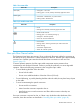
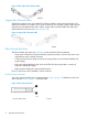
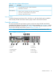
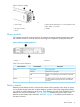
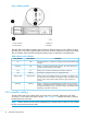

Table 1 Port status LEDs
DescriptionStatus LED
Green (left)
• Solid green— Active link
• Flashing green—Locate, remotely asserted by application client
Amber (right)
• Solid amber—Module fault, no synchronization
• Flashing amber—Module fault
Table 2 I/O module status LEDs
DescriptionStatus LED
• Locate
• Flashing blue—Remotely asserted by application client
• Module health indicator
• Flashing green—I/O module powering up.
• Solid green—Normal operation
• Green off—Firmware malfunction
• Fault indicator
• Flashing amber—Warning condition (not visible when solid
amber showing)
• Solid amber—Replace FRU
• Amber off—Normal operation
Fiber optic Fibre Channel cables
The Enterprise Virtual Array uses orange, 50-µm, multi-mode, fiber optic cables for connection to
the SAN or the host, where there is a direct connection to the host. The fiber optic cable assembly
consists of two 2-m fiber optic strands and small form-factor connectors on each end. See
Figure 5 (page 12).
To ensure optimum operation, the fiber optic cable components require protection from
contamination and mechanical hazards. Failure to provide this protection can cause degraded
operation. Observe the following precautions when using fiber optic cables.
• To avoid breaking the fiber within the cable:
Do not kink the cable◦
◦ Do not use a cable bend-radius of less than 30 mm (1.18 inch)
• To avoid deforming, or possibly breaking the fiber within the cable, do not place heavy objects
on the cable.
• To avoid contaminating the optical connectors:
Do not touch the connectors◦
◦ Never leave the connectors exposed to the air
◦ Install a dust cover on each transceiver and fiber cable connector when they are
disconnected
If an open connector is exposed to dust, or if there is any doubt about the cleanliness of the
connector, clean the connector as described in “Handling fiber optic cables” (page 43).
M6412A disk enclosures 11