
User guide


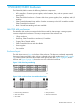
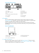

Figure 3 Disk enclosure rear view
7. I/O module B1. Power supply 1
8. Rear UID push button2. Power supply 1 status LED
9. Enclosure status LEDs3. Fan 1
10. Fan 24. Enclosure product number and serial number
11. Power push button5. Fan 1 status LED
12. Power supply 26. I/O module A
I/O modules
Two I/O modules provide the interface between the disk enclosure and the host controllers,
(Figure 4 (page 10)). For redundancy, only dual-controller, dual-loop operation is supported. Each
controller is connected to both I/O modules in the disk enclosure.
Each I/O module has two ports that can transmit and receive data for bidirectional operation.
Activating a port requires connecting a Fibre Channel cable to the port. The port function depends
upon the loop.
Figure 4 I/O module detail
4. Manufacturing diagnostic port1. Double 7–segment display: enclosure ID
5. I/O module status LEDs2. 4 Gb I/O ports
3. Port 1 (P1), Port 2 (P2) status LEDs
I/O module status indicators
There are five status indicators on the I/O module. See Figure 4 (page 10). The status indicator
states for an operational I/O module are shown in Table 1 (page 11). Table 2 (page 11) shows
the status indicator states for a non-operational I/O module.
10 EVA6400/8400 hardware