Router 5000 Family Installation Guide Router 5012 (3C13701) Router 5232 (3C13751) Router 5642 (3C13755) Router 5682 (3C13759) http://www.3com.com/ Part No. 10014373 Rev.
3Com Corporation 350 Campus Drive Marlborough, MA 01752-3064 Copyright © 2004, 3Com Corporation. All rights reserved. No part of this documentation may be reproduced in any form or by any means or used to make any derivative work (such as translation, transformation, or adaptation) without written permission from 3Com Corporation.
CONTENTS ABOUT THIS GUIDE Conventions 3 Related Documentation 1 4 INTRODUCING THE ROUTER 5000 FAMILY Router 5000 Family Software Router 5000 Family Hardware Router 5012 Hardware 8 Router 5232 Hardware 10 Router 5642 Hardware 11 Router 5682 Hardware 12 2 6 6 INSTALLING THE ROUTER Preparing to Install the Router 15 Mounting the Router in a Rack 18 Installing the Router on the Workbench 19 Connecting the Power Cable 19 Connecting the Router to the Console Terminal Installing SICs and MIMs 20 Connecting
5 TROUBLESHOOTING The Power LED is Off.
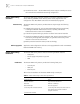
Conventions 3 ABOUT THIS GUIDE This guide describes the 3Com® Router 5000 Family of routers and how to install hardware, configure and boot software, and maintain software and hardware. This guide also provides troubleshooting and support information for your router. This guide is intended for the system or network administrator who is responsible for configuring, using, and managing the routers.
4 CHAPTER : ABOUT THIS GUIDE Table 2 Text Conventions Convention Description When you see the word “enter” in this guide, you must type something, and then press Return or Enter. Do not press Return or Enter when an instruction simply says “type.” Words in italics Italics are used to: Emphasize a point. Denote a new term at the place where it is defined in the text. Identify menu names, menu commands, and software button names. Examples: From the Help menu, select Contents.
1 INTRODUCING THE ROUTER 5000 FAMILY Routers in the 3Com Router 5000 Family support two types of interface modules: ■ Smart Interface Cards (SICs) — small WAN cards ■ Multifunctional Interface Modules (MIMs) — larger WAN cards The routers can be flexibly configured by changing or extending SICs or MIMs, to provide different functions.
6 CHAPTER 1: INTRODUCING THE ROUTER 5000 FAMILY ■ Router 5000 Family Software Data Security Online Upgrades Router 5000 Family Hardware Fixed Ports Fast Ethernet access — Router 5000 Family routers support 100 Mbps access to the local Ethernet and flexible networking configuration. The Router 5000 Family software operates in Synchronous Dynamic Random Access Memory (SDRAM). Flash memory stores router program files and configuration files. Boot ROM stores boot and initialization programs.
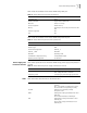
Router 5000 Family Hardware 7 Table 4 lists the attributes of the Router 5000 Family AUX port. Table 4 Router 5000 Family AUX Port Specifications Attribute Description Connector type RJ-45 Interface standard Asynchronous EIA/TIA-232 Baud rate 300 to 115.2 kbps Services supported Modem dial-up Backup Operating as the console port when the CON fails Protocols supported PPP SLIP MP Table 5 lists the attributes of the Router 5000 Family Ethernet port.
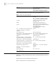
8 CHAPTER 1: INTRODUCING THE ROUTER 5000 FAMILY SLOT 1-3 ON-The MIM the SIC is powered and operating normally. OFF-No module is installed in the current slot or the module is not operating normally. Table 7 describes the LEDs on the Router 5232, 5642, 5682 routers. Table 7 Router 5232, 5642, 5682 LEDs POWER ON — The module (MIM or SIC) is operating normally. OFF — No module is installed in the current slot or the MIM is not operating normally.
Router 5012 Hardware 9 Figure 1 Front View of the Router 5012 Figure 2 illustrates the back of the Router 5012.
10 CHAPTER 1: INTRODUCING THE ROUTER 5000 FAMILY Table 9 lists the attributes of the Router 5012 synchronous/asynchronous serial port. Table 9 Synchronous/Asynchronous Serial Port Specifications Description Attribute Synchronous Asynchronous Connector type DB-50 Interface standard and operating mode V.24 V.35 EIA/TIA-232 DTE, DCE DTE DCE Minimum baud rate (bps) 1200 1200 1200 300 Maximum baud rate (bps) 64 k 2.048 M 2.048 M 115.
Router 5642 Hardware System Specifications 11 Table 10 lists the systems specifications for the Router 5232. Table 10 System Specifications for the Router 5232 Item Router 5232 specifications Fixed ports 1 AUX port 1 CONSOLE port 2 LAN port Slots 3 (MIM) Processor MPC 8245 300 MHz (AC power supply) NVRAM 128 KB Boot ROM 512 KB SDRAM 256 MB Flash 32 MB Dimensions (W x H x D) 442 x 44.4 x 413 mm (17.5 x 1.8 x 16.25 in) excluding rubber feet Weight 8kg (17.
12 CHAPTER 1: INTRODUCING THE ROUTER 5000 FAMILY Table 11 System Specifications for the Router 5642 (continued) Item Router 5642 specifications Fixed ports 1 AUX port 1 CONSOLE port Boot ROM 512 KB SDRAM 256 MB Flash 32 MB Dimensions (W x H x D) 442 x 44.4 x 413 mm (17.5 x 1.8 x 16.25 in) excluding rubber feet Weight 8 kg (17.64 lbs) Input voltage Rated voltage: 100-240 V a.c.; 50/60 Hz Maximum tolerance: 90-264 V a.c.; 50/60 Hz Router 5682 Hardware Max.
Router 5682 Hardware 13 Table 12 System Specifications for the Router 5682 Item Router 5682 specifications Fixed ports 1 AUX port 1 console port SDRAM 256 MB Flash 32 MB Dimensions (W x H x D) 442 x 91.2 x 413 mm (17.5 x 3.6 x 16.25 in) excluding rubber feet Weight 14 kg (30.86 lbs) Input voltage Rated voltage: 100-240 V a.c.; 50/60 Hz Maximum tolerance: 90-264 V a.c.; 50/60 Hz Max.
14 CHAPTER 1: INTRODUCING THE ROUTER 5000 FAMILY
2 INSTALLING THE ROUTER There are several ways you can install your router: ■ On a vertical surface ■ In a rack ■ On a workbench The following sections describe how to prepare and install your router: Preparing to Install the Router Safety Warnings ■ Preparing to Install the Router ■ Mounting the Router in a Rack ■ Installing the Router on the Workbench ■ Connecting the Power Cable ■ Connecting the Router to the Console Terminal ■ Installing SICs and MIMs ■ Connecting the Router to th
16 CHAPTER 2: INSTALLING THE ROUTER ■ During the installation, wear an Electro-Static Discharge (ESD) preventive wrist strap and ESD-preventive gloves. 3Com recommends that you use an uninterrupted power supply (UPS) with your router. General Site Requirements The environment of the installation site influences the performance and lifetime of the router.
Preparing to Install the Router 17 ■ The equipment room is dust-proof ■ Adequate temperature and humidity conditions prevail ■ The operator wears the ESD-preventive wrist strap, ESD-preventive gloves and ESD-preventive clothes while handling the circuit board. ■ The dismantled circuit board is placed upward on the ESD preventive workbench, or put into an ESD preventive bag. ■ You avoid direct contact with the elements of the circuit board.
18 CHAPTER 2: INSTALLING THE ROUTER ■ ■ Cables n Ethernet cable n Console cable n AUX cable n Power supply (for the Router 5012), power cord and chassis ground wire n Interface cables for the selected interface modules Equipment n A router n Optional SICs and MIMs n Ethernet 100BASE-T Hub or LAN switch n Channel service unit/data service unit (CSU/DSU) or other data communications equipment (DCE) equipment (such as a modem) n Configuration terminal, such as a PC n Additional equipme
Installing the Router on the Workbench Installing the Router on the Workbench 19 You can install any Router 5000 on a workbench. To install the router on a workbench, take the following precautions: Connecting the Power Cable ■ Ensure that the workbench is smooth and stable. ■ Leave a heat-dissipation clearance of 10 cm (4 in) around the router. ■ Do not put heavy objects on the router.
20 CHAPTER 2: INSTALLING THE ROUTER Figure 11 Connecting the Console Port to the PC (router shown for illustration only) PC serial interface PC Console cable Console port After connection, power on the router. The startup information of the router is displayed on the console terminal.
Connecting the Router to the Ethernet 21 Figure 12 Installing a SIC or MIM Connecting the Router to the Ethernet The Router 5000 Family routers provide a fixed 100BASE-TX fast Ethernet port that uses category-5 twisted pair cable. Note the following before you connect: ■ The fixed Ethernet cables are supplied with the router. ■ Use shielded cables to ensure electromagnetic compatibility. ■ Identify the mark on the module so you can plug the cable in correctly.
22 CHAPTER 2: INSTALLING THE ROUTER Figure 13 Connecting the Router to the Ethernet LAN switch or hub 10/100M Ethernet interface Ethernet cable ETHERNET0 interface Connecting the Router to the WAN The Router 5000 Family provides two fixed WAN ports, and gives you the option to install further WAN ports as required. The fixed ports are the AUX port and the serial port. The additional ports are provided by the SICs and MIMs supported by the Router.
Verifying the Installation 23 Use the following procedure to connect the serial cable (take the connection from SERIAL0 to DSU/CSU): 1 Turn off power to the router. 2 Choose the appropriate serial cable. 3 Plug the DB-50 adapter of the cable into the SERIAL0 port of the router. 4 Connect the other end of the cable to the CSU/DSU device. (If the WAN uses a dial-up line, connect the cable to the serial port of the analog modem.
24 CHAPTER 2: INSTALLING THE ROUTER
3 BOOTING AND CONFIGURING THE ROUTER During the initial configuration of the router, you can use only the console or AUX port. This chapter describes how to connect the router to a local or remote console terminal and how to set parameters at the console terminal.
26 CHAPTER 3: BOOTING AND CONFIGURING THE ROUTER Setting the Parameters of the Console Terminal To set terminal parameters: 1 Start the PC and select Start > Programs > Accessories > Communications > HyperTerminal. The HyperTerminal window displays the Connection Description dialog box, as shown below. Figure 18 Connection Description Dialog Box 2 Enter the name of the new connection in the Name field and click OK. The Connect To dialog box, shown below displays.
Setting the Parameters of the Console Terminal Figure 20 Connection Properties Dialog Box 4 Set the following parameters: Bits per second — 9600 Data bits — 8 Parity — None Stop bits — 1 Flow control — None. 5 Click OK. The HyperTerminal dialog box displays, as shown.
28 CHAPTER 3: BOOTING AND CONFIGURING THE ROUTER Figure 21 HyperTerminal Window 6 Select Properties. The Properties dialog box for your connection displays. 7 Click the Settings tab, as shown. Figure 22 Settings Tab 8 In the Emulation dropdown menu, select VT100 or Auto detect. Click OK.
Powering on the Router Powering on the Router 29 Before you power on the router, verify that: ■ The connection between the power cord and ground wire is secure ■ The voltage of the power supply complies with the requirement of the router ■ The console cable is correctly connected to either the PC or the terminal, and that the parameters are correct. Before switching on the power, locate the power-off switch in the workroom so that, in case of an electrical accident, power can be turned off quickly.
30 CHAPTER 3: BOOTING AND CONFIGURING THE ROUTER Startup Process After the router starts up, the Boot ROM program runs and the following information displays on the terminal screen: Booting ******************************************** * 3Com Router Boot Rom, V4.60 ******************************************** Copyright(C) 2002-2005 by 3Com Corporation, Inc. Compiled at 20:46:59 , Jan 23 2003. Now testing memory...
Configuration Fundamentals of the Router 31 3 Configure the WAN interface of the router: ■ Configure the physical operating parameters (the operating mode of the serial port, baud rate, and synchronous clock) of the interface according to the transmission medium of the WAN. For the dial-up port, you need to configure DDR parameters. ■ Configure the link layer protocol encapsulated on the interface and the related operating parameters according to the type of the WAN.
32 CHAPTER 3: BOOTING AND CONFIGURING THE ROUTER To facilitate the management of the router in the system view, all the commands are grouped. Each group corresponds to a view. Users can use these commands to switch between different views. Many commands are limited to use in a single view. Other commands (such as ping, display current-configuration, interface) can be executed in all views.
MAINTAINING THE ROUTER 4 Introduction The files managed by the Router 5000 are of 3 types: ■ Boot ROM program files used by the Router to boot the application program files ■ Application files (main software) ■ Configuration files This chapter will introduce you with three methods: Boot Menu ■ Application and Boot ROM programs upgrade via XModem ■ Application program upgrade via TFTP ■ Application program and configuration file upload/download via FTP Boot Menu: 1: Download application progr
34 CHAPTER 4: MAINTAINING THE ROUTER 4 Clear application program password. This option clears super user password. This option functions for only one time and password authentication for super users is restored after the router is rebooted. 5 Ignore configuration file and start up with initial configuration. 6 Enter debugging environment in case of faults. 7 Boot menu provides two methods for upgrading the program and the Boot ROM sub-menu operations, which are introduced in the following subsections.
Introduction 35 Downloading ... CCCCC After the baud rate at the console terminal is set, the new setting can become valid only if the terminal emulation program is disconnected and reconnected for at least once. 4 Select [Transmit/send file] in the terminal window and the following dialog box will pop up: Figure 24 Send File dialog box 5 Click , select the application file to be downloaded, and set the protocol to Xmodem.
36 CHAPTER 4: MAINTAINING THE ROUTER Please use 9600 bps.Press key to reboot the system. Then restore the baudrate of the configuration terminal to 9600bps as per the prompt (disconnection and re-dialing are also required here), and then the system start up normally. Upgrading the entire Boot ROM program 1 Enter Boot menu, select <7> to turn to Boot ROM operation menu. 2 Select <1> in the Boot ROM operation sub-menu to download the Boot ROM program with XModem.
Introduction Upgrading Application Program with Ethernet 37 It refers to downloading application program through Ethernet port. The router serves as client, so it needs to be connected to TFTP Server or FTP Server through its fixed Ethernet port. The following are the details. CAUTION: TFTP Server or FTP Server program is not included in 5000 Family routers, so you have to buy and install it. Both TFTP loading and FTP loading are available in 5000 Family routers.
38 CHAPTER 4: MAINTAINING THE ROUTER flags (f): The flag must be 0x0 for FTP mode These parameters will be saved automatically when your configuration is completed. Router restarts after successful upgrading Press to return to NET download menu and select <2>, and then this information is prompted: boot device unit number processor number host name file name inet on ethernet (e) host inet (h) user (u) ftp password (pw) flags (f) : : : : : : : : : : fei 0 0 8040 Q8040.BIN 10.110.27.235 10.110.27.
Introduction 39 Build up FTP local upload/download environment Figure 26 Building up FTP local upload/download environment 1 Connect the Ethernet interface on the router to the PC. 2 Assign an IP address for the Ethernet interface on the router. It is assumed to be 10.110.10.10. 3 Assign an IP address for the Ethernet interface on the PC. It is assumed to be 10.110.10.13. 4 Copy the application files, Boot ROM program or configuration files to a directory, which is assumed to be "C:\ version".
40 CHAPTER 4: MAINTAINING THE ROUTER Starting the FTP server Perform the following configurations with the help of the maintenance personnel at the router side: 1 Set authentication mode You can select an AAA configuration scheme depending on the actual situation. F 2 Add user name and password [Router] local-user router password simple 123 service-type ftp "Router" represents the user name and "123" the password.
Introduction 41 Upload the application program file or Boot ROM program or configuration file. ftp>put local file (Input the name of appplication/Boot ROM program/Configuration file to be uploaded.) remote file (Input the name of appplication/Boot ROM program/Configuration file to be saved at the router side after uploading.) After the uploading is completed, the prompt "ftp>" will be displayed again. Enter
to display the name and size of the file on the router.42 CHAPTER 4: MAINTAINING THE ROUTER Figure 28 Installing a Module Closing the Router Chassis Cover To prevent cables from being pressed or cut off when you close the cover of the router chassis, roll up all the cables and put them into the chassis before closing the cover.
5 The Power LED is Off. TROUBLESHOOTING If the power LED is off, verify that: ■ The power switch of the router is turned on. ■ The power supply switch is turned on. ■ The power cord of the router is connected properly. ■ The power supply suits the requirement of the router. Do not plug in or unplug the power cord when the power is on. After having checked the conditions in the previous list, if the power LED is still off, contact your Service representative.
44 CHAPTER 5: TROUBLESHOOTING Illegible Characters Display on the Terminal after Power-On If the system operates normally after the system runs the POST, the start-up information is displayed on the console terminal. If the configuration system has a fault, the terminal may display only illegible characters.
Troubleshooting SICs and MIMs 45 may be out of order. In such a case and you should contact your Service representative. After Startup, All LEDs Remain On. After startup, all LEDs should once, which indicates that the processor of the module is in operation. If all LEDs are on, the module’s system bus is not operating normally or the CPLD is out of order. The RUN LED Remains On. When the module is in operation, the RUN LED should blink, rather than remain on.
46 CHAPTER 5: TROUBLESHOOTING
A CABLE SPECIFICATIONS The tables in this appendix describe the pinouts for the cables that you can use with Router 5000 Family routers. Pins that are not described in the following tables are not connected.
48 APPENDIX A: CABLE SPECIFICATIONS AUX Cable Figure 29 AUX Cable Assembly Enlarged A side DB25 Male 8P8C Plug Label Enlarged B side DB9Male Enlarged C side Table 17 RJ-45 Ethernet Cable Signal Direction DB-25 DB-9 Signal 1 —> 4 7 RTS 2 —> 20 4 DTR 3 —> 2 3 TXD 4 <— 8 1 DCD 5 - 7 5 GND 6 <— 3 2 RXD 7 <— 6 6 DSR 8 <— 5 8 CTS The Ethernet cable uses an RJ-45 connector and category 5 twisted pair cable.
Ethernet Cable 49 Table 18 Straight-through Network Cable Pinouts Category 5 twisted pair RJ-45 Signal Signal Direction RJ-45 1 TX+ White (Orange) —> 1 2 TX- Orange —> 2 3 RX+ White (Green) <— 3 4 - Blue - 4 5 - White (Blue) - 5 6 RX- Green <— 6 7 - White (Brown) - 7 8 - Brown - 8 Table 19 Crossover Network Cable Pinouts Category 5 Twisted Pair RJ-45 Signal Signal Direction RJ-45 1 TX+ White (Orange) —> 3 2 TX- Orange —> 6 3 RX+ White (Green) <—
50 APPENDIX A: CABLE SPECIFICATIONS Serial Interface Cable Synchronous and Asynchronous Mode V.35 and V.24 (EIA/TIA-232) standards support synchronous operating mode. V.24 (EIA/TIA-232) also supports the asynchronous operating mode. The maximum transmission distance and baud rate of the signal vary with the operating mode. Table 20 Transmission Rate and Transmission Distance of V.24 (EIA/TIA-232)/V.35 Cable V.24 (EIA/TIA-232) Baud rate (bps) V.
Serial Interface Cable 51 At the network end, the connector is different for each type of cable, as described in the following list: V.24 DTE Cable Assembly and Pinouts ■ V.24 (EIA/TIA-232) DTE cable — DB-25 (male) adapter ■ V.24 (EIA/TIA-232) DCE cable — DB-25 (female) adapter ■ V.35 DTE cable — 34-pin (male) adapter ■ V.35 DCE cable — 34-pin (female) adapter Figure 31 illustrates the V.24 DTE cable assembly. Figure 31 V.
52 APPENDIX A: CABLE SPECIFICATIONS V.24 DCE Cable Assembly and Pinouts Figure 32 illustrates the V.24 DCE cable assembly. Figure 32 V.24 DCE Cable Assembly DB25 Male Enlarged A side DB50 Male Enlarged B side Label Table 23 describes the V.24 DCE cable pinouts. Table 23 V.
Serial Interface Cable V.35 DTE Cable Assembly and Pinouts 53 Figure 33 illustrates the V.35 DTE cable assembly. Figure 33 V.35 DTE Cable Assembly V.35 Male Enlarged A side DB50 Male Label Enlarged B side Table 24 describes the V.35 DTE cable pinouts. Table 24 V.
54 APPENDIX A: CABLE SPECIFICATIONS V.35 DCE Cable Assembly and Pinouts Figure 34 illustrates the V.35 DCE cable assembly. Figure 34 V.35 DCE Cable Assembly V.35 Female Enlarged A side DB50 Male Label Enlarged B side Table 25 describes V.35 DCE cable pinouts. Table 25 V.
Dumb Terminal Adapter Dumb Terminal Adapter Table 26 describes dumb terminal adapter pinouts. Table 26 Dumb Terminal Adapter Pinouts RJ-45 (female) E1 Cable DB-25 (female) Signal 1 8 DCD 2 6 DSR 3 20 DTR 4 7 GND 5 2 TxD 6 3 RxD 7 4 RTS 8 5 CTS Table 27 describes E1 cable pinouts. In this table, Tx = transmit and Rx = receive. These markings on 75-ohm coaxial cables are in relation to the routers, and they should be connected to the peer's “Tx” and “Rx”.
56 APPENDIX A: CABLE SPECIFICATIONS ISDN cables The ISDN S/T cable, shown in Figure 35, is a 4-core twisted pair cable. Both ends of the cable have RJ-45 connectors in which pin 3 and pin 6 are the sending end, and pin 4 and pin 5 are the receiving end. Figure 35 ISDN S/T Cable The ISDN U cable, shown in Figure 36, is a 2-core twisted pair cable. One end has an RJ11 connector and the other end has an output terminal (OT) connector.
A Register Your Product OBTAINING SUPPORT FOR YOUR PRODUCT Warranty and other service benefits start from the date of purchase, so it is important to register your product quickly to ensure you get full use of the warranty and other service benefits available to you. Warranty and other service benefits are enabled through product registration. Register your product at http://eSupport.3com.com/. 3Com eSupport services are based on accounts that you create or have authorization to access.
58 APPENDIX A: OBTAINING SUPPORT FOR YOUR PRODUCT Software Upgrades are the software releases that follow the software version included with your original product. In order to access upgrades and related documentation you must first purchase a service contract from 3Com or your reseller. Telephone Technical Support and Repair To obtain telephone support as part of your warranty and other service benefits, you must first register your product at http://eSupport.3com.
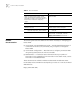
Contact Us Country Telephone Number Country Or request a repair authorization number (RMA) by fax using this number: Telephone Number + 65 543 6348 Europe, Middle East, and Africa Telephone Technical Support and Repair From anywhere in these regions, call: +44 (0)1442 435529 From the following countries, you may use the numbers shown: Austria Belgium Denmark Finland France Germany Hungary Ireland Israel Italy 01 7956 7124 070 700 770 7010 7289 01080 2783 0825 809 622 01805 404 747 06800 12813 1407
60 APPENDIX A: OBTAINING SUPPORT FOR YOUR PRODUCT