
Command Reference Guide


3Com Router 5000 Family and Router 6000 Family display controller cpos t1 ● 81
Command Reference
display controller cpos t1
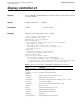
Purpose Use the display controller cpos t1 command to view the physical layer
configuration information of a specified T1 channel on the specified CPOS interface.
Syntax display controller cpos cpos-number t1 t1-number
Parameters t1-number
Number of a T1 channel on a CPOS interface. Valid
values are 1 to 84.
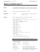
Example View the state about the T1 channel 2 on the interface CPOS 4/0/0.
<3Com > display controller cpos 4/0/0 t1 2
Cpos4/0/0 current state : UP Frame-format SDH, multiplex AU-3, clock
master, loopback not set
Tx: J0: 0x01, J1: "NetEngine", C2: 0x02
Rx: J0: 0x01, J1: "NetEngine", C2: 0x02
Regenerator section:
Alarm: none
Error: 0 BIP, 0 SEF
Multiplex section:
Alarm: none
Error: 0 BIP, 0 REI
Higher order path(VC-3-2):
Alarm: none
Error: 0 BIP, 0 REI
Lower order path:
Alarm: none
Error: 4095 BIP, 2047 REI
Cpos4/0/0 CT1 2 is up
Frame-format ESF, clock master, loopback not set
T1 framer(2-1-1):
Alarm: none
Error: 4095 FERR, 79 AERR
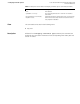
The following table describes the displayed information:
Table 1 Description on the fields of the display controller cpos t1 command
Field Description
Cpos1/0/0 current state : The current physical state of the CPOS interface
Frame-format SDH, multiplex AU-3,
clock master, loopback not set
Physical layer information of the CPOS interface.
Tx: J0: 0x01, J1: "NetEngine",
C2: 0x02
The sent overhead bytes
Rx: J0: 0x01, J1: "NetEngine",
C2: 0x02
The received overhead bytes
Regenerator section: Alarms and errors about the regenerator sections.
Multiplex section: Alarms and errors about the regenerator sections.
Higher order path(VC-3-2): Alarm and error statistic of the higher-order path to which
the T1 channel belongs. VC-3-2 means the second VC-3.
Lower order path: Alarm and error statistic of the lower-order path