
Command Reference Guide


3Com Router 5000 Family and Router 6000 Family display controller cpos e1 ● 79
Command Reference
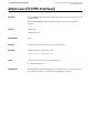
display controller cpos e1
Purpose Use the display controller cpos e1 command to view the physical layer
configuration information of a specified E1 channel on the specified CPOS interface.
Syntax display controller cpos cpos-number e1 e1-number
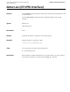
Parameters e1-number
Number of an E1 channel on a CPOS interface. Valid
values are 1 to 63.
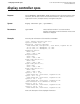
Example View state about E1 channel 1 on the interface CPOS 1/0/0.
<3Com > display controller cpos 1/0/0 e1 1
Cpos1/0/0 current state : UP
Description : Cpos1/0/0 Interface
Frame-format SDH, multiplex AU-4, clock master, loopback not set
Tx: J0: 0x01, J1: "NetEngine", C2: 0x02
Rx: J0: 0x01, J1: "NetEngine", C2: 0x02
Regenerator section:
Alarm: none
Error: 0 BIP, 0 SEF
Multiplex section:
Alarm: none
Error: 0 BIP, 0 REI
Higher order path(VC-4-1):
Alarm: none
Error: 0 BIP, 0 REI
Lower order path:
Alarm: none
Error: 0 BIP, 0 REI
Cpos2/0 CE1 1 is up
Frame-format NO-CRC4, clock slave, loopback not set
E1 framer(1-1-1-1):
Alarm: none
Error: 0 FERR, 0 FEBE, 0 AERR
Where, “E1 framer(1-1-1-1)” presents how the E1 channel is multiplexed. 1-1-1-1
represents the number of VC-4 to which this E1 channel belongs, TUG-3 number,
TUG-2 number, and TUG-12 number in order.
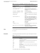
View This command can be used in the following views:
■ Any view