
Service and Maintain


Feet
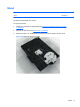
Description Spare part number
Foot, right 646784-001
Foot, left 646785-001
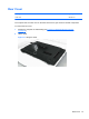
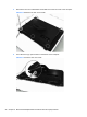
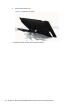
Each foot is connected to the computer with one screw. The top of the foot is positioned under the
display panel bracket. You must slide the foot out from under the bracket to remove it, and place it
back under the bracket to install it.
To remove the feet:
1. Prepare the computer for disassembly (see
Preparing to Disassemble the Computer
on page 26).
2. Remove the rear cover (see
Rear Cover on page 27).
3. For each foot, remove the Torx T15 3.0x6.0 screw (1) that secures the foot to the computer.
4. Slide the foot away out from under the display panel bracket and away from the computer (2).
Figure 6-5 Removing the feet (right foot shown)
To replace the feet, reverse the removal procedures.
When reinstalling a foot, make sure you slide the top of the foot under the display panel bracket
before securing the screw.
30 Chapter 6 Removal and Replacement Procedures All-in One (AIO) Chassis