OfficeConnect® ADSL Wireless 108Mbps 11g Firewall Router User Guide Model WL-553 3CRWDR200A-75 3CRWDR200B-75 www.3Com.com Part Number: 10015251 Rev.
3Com Corporation 350 Campus Drive Marlborough, MA USA 01752-3064 Copyright © 2006, 3Com Corporation. All rights reserved. No part of this documentation may be reproduced in any form or by any means or used to make any derivative work (such as translation, transformation, or adaptation) without written permission from 3Com Corporation.
CONTENTS ABOUT THIS GUIDE Naming Convention 7 Conventions 8 Feedback about this User Guide Related Documentation 9 1 9 INTRODUCING THE ROUTER OfficeConnect ADSL Wireless 108Mbps 11g Firewall Router Firewall Router Advantages 13 Package Contents 13 Minimum System and Component Requirements 15 Front Panel 15 Rear Panel 17 2 HARDWARE INSTALLATION Introduction 19 Safety Information 19 Positioning the Router 19 Using the Rubber Feet 20 Stacking the Router 20 Wall Mounting 20 Before you Install your Router
Windows 95/98/ME 27 Macintosh 27 Disabling PPPoE and PPTP Client Software Disabling Web Proxy 28 4 RUNNING THE SETUP WIZARD Accessing the Wizard 29 Password 32 Time Zone 33 ATM PVC Configuration IGMP 34 Connection Mode 34 LAN Settings 39 Wireless Settings 41 Summary 42 5 28 33 ROUTER CONFIGURATION Navigating Through the Router Configuration Pages Main Menu 45 Option Tabs 46 Welcome Screen 46 Notice Board 47 Password 47 Wizard 48 LAN Settings 49 Unit Configuration 49 DHCP Lease Table 50 Wireless Settin
Virtual Servers 62 Special Applications 63 Virtual DMZ 64 SPI 65 Internet Access Policy 67 Content Filter 69 System Tools 70 Restart 70 Time Zone 71 Configuration 72 Upgrade 73 Advanced 73 Routing 74 Static Route 74 RIP 75 DNS 77 DDNS 77 DSL 79 IPSec 79 Proxy ARP 80 ALG 81 Management 82 Syslog 82 SNMP 83 Trusted Station 84 Remote Management 84 Diagnostics 85 Device Info 86 Summary 86 WAN 86 Statistics 87 Route 87 ARP 88 Support/Feedback 88 Support 89 Feedback 89 iii
TROUBLESHOOTING Basic Connection Checks 91 Browsing to the Router Configuration 91 Connecting to the Internet 92 Forgotten Password and Reset to Factory Defaults Wireless Networking 94 Replacement Power Adapters 96 Alert LED 97 Recovering from Corrupted Software 97 Frequently Asked Questions 98 A USING THE 3COM DISCOVERY TOOL Running the Discovery Application 101 Windows Installation (95/98/2000/Me/NT) B 93 101 IP ADDRESSING The Internet Protocol Suite 103 Managing the Router over the Network 103 I
C SAFETY INFORMATION D END USER SOFTWARE LICENSE AGREEMENT E ISP INFORMATION GLOSSARY REGULATORY NOTICES FOR THE ADSL WIRELESS 108MBPS 11G FIREWALL ROUTER INDEX v
vi
ABOUT THIS GUIDE This guide describes how to install and configure the OfficeConnect ADSL Wireless 108Mbps 11g Firewall Router (3CRWDR200A-75 and 3CRWDR200B-75). This guide is intended for use by those responsible for installing and setting up network equipment; consequently, it assumes a basic working knowledge of LANs (Local Area Networks) and Internet Router systems.
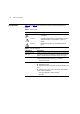
8 ABOUT THIS GUIDE Conventions Table 1 and Table 2 list conventions that are used throughout this guide. Table 1 Notice Icons Icon Notice Type Description Information note Information that describes important features or instructions. Caution Information that alerts you to potential loss of data or potential damage to an application, system, or device. Warning Information that alerts you to potential personal injury.
Feedback about this User Guide Feedback about this User Guide 9 Your suggestions are very important to us. They will help make our documentation more useful to you. Please e-mail comments about this document to 3Com at: pddtechpubs_comments@3com.
10 ABOUT THIS GUIDE
1 INTRODUCING THE ROUTER Welcome to the world of networking with 3Com®. In the modern business environment, communication and sharing information is crucial. Computer networks have proved to be one of the fastest modes of communication but, until recently, only large businesses could afford the networking advantage. The OfficeConnect® product range from 3Com has changed all this, bringing networks to the small office.
12 CHAPTER 1: INTRODUCING THE ROUTER Figure 1 Example Network Without a Firewall Router When you use the Firewall Router in your network (Figure 2), it becomes your connection to the Internet. Connections can be made directly to the Router, or to an OfficeConnect Switch or Hub, expanding the number of computers you can have in your network.
Firewall Router Advantages Firewall Router Advantages 13 The advantages of the Firewall ADSL Wireless 108Mbps 11g Firewall Router include: Shared Internet connection for both wired and wireless computers High speed 802.
14 CHAPTER 1: INTRODUCING THE ROUTER One RJ 45 cable (typically an Ethernet cable) if your model is 3CRWDR200B-75 One Product Range Sheet One CD-ROM containing the Firewall Router Discovery program and this User Guide Installation Guide One Support and Safety Information Sheet One Warranty Flyer If any of these items are missing or damaged, please contact your retailer.
Minimum System and Component Requirements Minimum System and Component Requirements 15 Your Router requires that the computer(s) and components in your network be configured with at least the following: A computer with an operating system that supports TCP/IP networking protocols (for example Windows 95/98/NT/Me/2000/XP, Unix, Mac OS 8.5 or higher). An Ethernet 10Mbps or 10/100 Mbps NIC for each computer to be connected to the four-port switch on your Router. An 802.11b or 802.11g wireless NIC.
16 CHAPTER 1: INTRODUCING THE ROUTER Flashing quickly - Indicates one of the following conditions: The Router has just been started up and is running a self-test routine, or The administrator has invoked the Reset to Factory Defaults command, or The system software is in the process of being upgraded In each of these cases, wait until the Router has completed the current operation and the alert LED is Off.
Rear Panel 17 transmitted or received. If the LED is off, nothing is connected, the connected device is switched off, or there is a problem with the connection (refer to Chapter 6 “Troubleshooting”). The port will automatically adjust to the correct speed and duplex. 5 Cable/DSL Status LED Green (100 Mbps link) / yellow (10 Mbps link) If the LED is on, the link between the Router and the cable or DSL modem is OK. If the LED is flashing, the link is OK and data is being transmitted or received.
18 CHAPTER 1: INTRODUCING THE ROUTER Only use the power adapter supplied with this Router. Do not use any other adapter. 9 Power Adapter OK LED Green Indicates that the power adapter is supplying power to the Router. If the LED is off, there may be a problem with the power adapter or adapter cable. 10 Reset Button Press this button for resetting your Router to factory default.
2 Introduction HARDWARE INSTALLATION This chapter will guide you through a basic installation of the Router, including: Connecting the Router to the Internet. Connecting the Router to your network. Setting up your computers for networking with the Router. Safety Information WARNING: Please read the Router section in Appendix C before you start. VORSICHT: Bitte lesen Sie den Abschnitt “Wichtige Sicherheitshinweise” sorgfältig durch, bevor Sie das Gerät einschalten.
20 CHAPTER 2: HARDWARE INSTALLATION allows easy viewing of the front panel LED indicator lights, and access to the rear panel connectors, if necessary. When positioning your Router, ensure: It is out of direct sunlight and away from sources of heat. Cabling is away from power lines, fluorescent lighting fixtures, and sources of electrical noise such as radios, transmitters and broadband amplifiers. Water or moisture cannot enter the case of the unit.
Before you Install your Router 21 You will need two suitable screws to wall mount the unit. To do this: 1 Ensure that the wall you use is smooth, flat, dry and sturdy and make two screw holes which are 150 mm (5.9 in.) apart. 2 Fix the screws into the wall, leaving their heads 3 mm (0.12 in.) clear of the wall surface. 3 Remove any connections to the unit and locate it over the screw heads. When in line, gently push the unit on to the wall and move it downwards to secure.
22 CHAPTER 2: HARDWARE INSTALLATION You should leave the Authentication Method as its default: Auto if your ISP doesn’t specify this parameter. If your ISP allocates fixed or static IP information, you need the following information: IP Address : ____.____.____.____ Subnet Mask : ____.____.____.____ Default Router address : ____.____.____.____ DNS address : ____.____.____.____ If your ISP allocates IP information dynamically over a protocol other than PPPoE, you do not need any further information.
Connecting the Router Connecting the Router 23 The first step for installing your Router is to physically connect it to a RJ11 cable with the splitter and then connect the Router to a computer in order to be able to access the Internet. See Figure 5: Figure 5 Connecting the Router sofu Power Supply Unit Jouf Telephone socket 12VDC 1.
24 CHAPTER 2: HARDWARE INSTALLATION To communicate wirelessly with your Router, your wireless NIC should be set as follows: Encryption — none Service Area Name/SSID — 3Com Channel — 11
4 Accessing the Wizard RUNNING THE SETUP WIZARD The Firewall Router setup program is Web-based, which means that it is accessed through your Web browser (Netscape Navigator 4.7 or higher, Internet Explorer 5.0 or higher, or Mozilla 1.2.1 or higher). To use the Setup Wizard: 1 Ensure that you have at least one computer connected to the Firewall Router. Refer to Chapter 2 for details on how to do this. 2 Launch your Web browser on the computer.
30 CHAPTER 4: RUNNING THE SETUP WIZARD Figure 10 Firewall Router Login Screen 5 If the password is correct, the Country Selection screen will appear. Select the country you wish to configure the Firewall Router for, then click Apply. (Figure 11) If your purchased your Firewall Router in the United States, you do not see this screen, as it is automatically set.
Accessing the Wizard 31 The Welcome screen will appear (Figure 12). Select the Wizard tab and click Wizard. or If your Router has not been configured before, the Wizard will launch automatically (refer to Figure 13). 7 Click Next. 8 You will be guided step by step through a basic setup procedure.
32 CHAPTER 4: RUNNING THE SETUP WIZARD Figure 13 Wizard Screen Password Figure 14 Change Administration Password Screen When the Change Administration Password screen (Figure 14) appears, type the Old Password, then a new password in both the New Password and Confirm Password boxes. 3Com recommends entering a new password when setting up the Firewall Router for the first time. The Firewall Router is shipped from the factory with a default password, admin. 1. Password is case sensitive.
Accessing the Wizard 33 2. Write the new password down and keep it in a safe place, so that you can change your settings in the future. Click Next to display the Time Zone setup screen (Figure 15). Time Zone Figure 15 Time Zone Screen Select your time zone from the pull-down menu, check the daylight savings option if required, and then click Next. The Daylight Savings option advances the system clock by one hour. It does not cause the system clock to be updated for daylight savings time automatically.
34 CHAPTER 4: RUNNING THE SETUP WIZARD communications applications. The UBR service may be considered as "best effort service". Peak cell rate specifies the maximum cell rate at which the user will transmit. CBR (constant bit rate): the CBR service class is intended for real-time applications, for example, those requiring tightly constrained delay and delay variation, such as voice and video applications.
Accessing the Wizard 35 PPPoE/PPPoA is required (typically DSL users only) see page 35 IP over ATM (IPoA, using ATM networks as the underlying data link for IP networks, defined by IETF RFC 1577) see page 38 MAC Encapsulation Routing (MER) see page 37 Bridging, see page 39 and click Next.
36 CHAPTER 4: RUNNING THE SETUP WIZARD Do not enter anything in this box if your ISP does not require a service name. 4 Select PPP Authentication Method from the drop-down menu. 5 Dial on Demand: Check the box to make a connection while in demand. Enter the Inactivity Timeout to cut off the network connection if there is no activity for this router. 6 PPP IP extension: Check this box to invoke the PPP IP extension. Only one user is allowed to access the web configurator at one time when this is checked.
Accessing the Wizard 37 MER Mode Figure 18 MER screen MER mode is used in business environment where static IP address and subnet are assigned by your ISP. Choose MER and click Next. To setup the Firewall Router for use with a MER connection, use the following procedure: Obtain an IP address automatically: Click this button to make the system get an IP address automatically. Manually entering an IP address: To set WAN IP address by yourself.
38 CHAPTER 4: RUNNING THE SETUP WIZARD 7 Configuring LAN setting: See “LAN Settings” in this section for more information. IPoA Mode Figure 19 IPoA Mode Screen To setup the Firewall Router for use with a IPoA connection, use the following procedure: 1 Enter the IP Address for WAN interface. 2 Enter the Subnet Mask for WAN interface. 3 Enter your Primary DNS Address and Secondary DNS address. Your ISP may provide you with primary and secondary DNS addresses.
Accessing the Wizard 39 Bridging Mode Figure 20 Bridging Mode Screen To set up the Firewall Router for use as a bridge in which the router is the bridge between WAN and LAN, use the following procedure: 1 Enter the name for the bridging service. 2 Enter the IP Address and Subnet Mask for the LAN. See “LAN Settings” LAN Settings Figure 21 LAN IP Address Screen This screen displays a suggested LAN IP address and subnet mask of the Firewall Router.
40 CHAPTER 4: RUNNING THE SETUP WIZARD 4 Configure the second IP Address and Subnet Mask for the LAN interface: Check this box to make another set of IP Address and Subnet Mask to connect to your router if they are not included in the range of DHCP server. 5 Enter the Secondary IP Address and Subnet Mask. DHCP The Firewall Router contains a Dynamic Host Configuration (DHCP) server that can automatically configure the TCP/IP settings of every computer on your network.
Accessing the Wizard Wireless Settings 41 Figure 23 Wireless Configuration Screen This screen displays the Channel and Service Area Name. It also allows you to change these settings. There are a maximum of 14 channels, the number available to you is dependent on the country you reside in. Selecting Clear Channel Select from the Channel drop-down list allows the Firewall Router to automatically select an available channel when first powered on. The Service Area Name default for 3Com products is “3Com”.
42 CHAPTER 4: RUNNING THE SETUP WIZARD channel you select as this may be useful if you experience problems with your clients. Summary Figure 24 Configuration Summary Screen When you complete the Setup Wizard, a configuration summary will display. 3Com recommends that you verify the configuration information of the Firewall Router and then print this page for your records.
Accessing the Wizard 43 Figure 25 Wizard Completed Screen If you have made changes to the LAN Settings or wireless configuration options, you may need to reconfigure the computer you are using in order to make contact with the Firewall Router again. Your Firewall Router is now configured and ready for use. For information on improving your Wireless network security see "Wireless Settings" on page 50. See Chapter 5 for a detailed description of the Router configuration screens.
44 CHAPTER 4: RUNNING THE SETUP WIZARD
3 SETTING UP YOUR COMPUTERS The Router has the ability to dynamically allocate network addresses to the computers on your network, using DHCP. However, your computers need to be configured correctly for this to take place. To change the configuration of your computers to allow this, follow the instructions in this chapter.
26 CHAPTER 3: SETTING UP YOUR COMPUTERS Figure 6 Local Area Properties Screen 6 Ensure that the options Obtain an IP Address automatically, and Obtain DNS server address automatically are both selected as shown in Figure 7. Click OK. Figure 7 Internet Protocol (TCP/IP) Properties Screen 7 Restart your computer.
Obtaining an IP Address Automatically Windows XP 27 If you are using a Windows XP computer, use the following procedure to change your TCP/IP settings: 1 From the Windows Start menu, select Control Panel. 2 Click on Network and Internet Connections. 3 Click on the Network Connections icon. 4 Double click on LAN or High Speed Connection icon. A screen titled Local Area Connection Status will appear. 5 Select Internet Protocol TCP/IP and click on Properties.
28 CHAPTER 3: SETTING UP YOUR COMPUTERS Disabling PPPoE and PPTP Client Software If you have PPPoE or PPTP client software installed on your computer, you will need to disable it. To do this: 1 From the Windows Start menu, select Settings > Control Panel. 2 Double click on Internet Options. 3 Select the Connections Tab. A screen similar to Figure 8 should be displayed. 4 Select the Never Dial a Connection option.
5 ROUTER CONFIGURATION Navigating Through the Router Configuration Pages Main Menu This chapter describes all the screens available through the Router configuration pages, and is provided as a reference. To get to the configuration pages, browse to the Router by entering the URL in the location bar of your browser. The default URL is http://192.168.1.1 but if you changed the Router LAN IP address during initial configuration, use the new IP address instead.
46 CHAPTER 5: ROUTER CONFIGURATION System Tools — allows the administrator to perform maintenance activities on the Router. Advanced — allows the administrator to monitor and configure the Router’s advanced features, including Static Routing, DSL, RIP, DDNS, IPSec, Proxy ARP, and ALG. Management — displays the current status and activity logs of the Router, SNMP enable/disable, Internet service enable/disable, and remote management control.
Welcome Screen Notice Board 47 Figure 26 Notice Board Screen The Notice Board is used to display the firmware version and configuration warning messages. For example, you would be warned if you had disabled wireless networking or wireless encryption.
48 CHAPTER 5: ROUTER CONFIGURATION Changing the Administration Password You can change the password to prevent unauthorized access to the Administration System. To do this: 1 Enter the current password in the Old Password field 2 Enter the new password in the New Password field 3 Enter the new password again in the Confirm Password field 4 Click Save/Apply to save the new password The password is case sensitive. If you have forgotten your password you need to reset the Router.
LAN Settings 49 LAN Settings Unit Configuration Figure 29 LAN Setup Screen This screen allows you to change the IP address and subnet mask. 1 IP Address: Enter the IP Address for your LAN interface. 2 Subnet Mask: Enter the Subnet Mask for your LAN interface. 3 Enable IGMP Snooping: The Internet Group Management Protocol snooping can snoop on IGMP query, report and leave packets transferred between IP Multicast Routers/Switches to learn the IP Multicast group membership.
50 CHAPTER 5: ROUTER CONFIGURATION Subnet Mask to connect to your router if they are not included in the range of DHCP server. 7 Enter the Secondary IP Address and Subnet Mask. DHCP Lease Table Figure 30 DHCP Lease Table Screen The DHCP Lease table screen list the client’s name, MAC Address, IP Address and Expiration time which reflects the value specified in DHCP server setting in “Unit Configuration” on this chapter.
Wireless Settings Configuration 51 Figure 31 Enabling Wireless Screen Enable Wireless Networking Use this check box to enable or disable the wireless section of your LAN. When disabled, no wireless PCs can gain access to either the Internet or other PCs on your Wired or Wireless LAN through this Router. Wireless Mode Select a mode from the drop-down list to configure your wireless networks. The Router supports 11b, 11g, Super G, and Mixed 11b/11g which is the default.
52 CHAPTER 5: ROUTER CONFIGURATION Valid channels are country dependent. See “Channels” on page 125 for a list of channels approved by each country. Service Area Name/SSID This allows you to name your Wireless network. The Service Area Name/SSID field will accept any alphanumeric string and has a maximum length of 32 characters. Your Wireless computers must be configured with exactly the same name or you will not establish a connection.
Wireless Settings 53 After you have finished configuring your Router, click on Save to save your existing changes or Cancel to revert your changes. Encryption Figure 32 Encryption Screen When setting up wireless networks, it is important to remember that with encryption disabled, anyone with a Wireless PC can eavesdrop on your network. 3Com recommends that you get the network working with encryption disabled first and then enable it as the last step. This will simplify setting up your network.
54 CHAPTER 5: ROUTER CONFIGURATION WPA/WPA2/Mixed WPA WPA2 +Radius PSK2+RADIUS features using of a RADIUS server with the pre-shared key authentication method. (This should only be used when a RADIUS server is connected to the Router). WPA provides a higher level of security, provided by its longer key and dynamic changes made to the key over time. 3Com recommends that you use WPA with any clients which support it.
Wireless Settings Using the Radius Server Figure 33 WPA/WPA2 Encryption Screen - Radius Server To set up WPA/WPA2/Mixed WPA and WPA2 with Radius Server: 1 Select Encryption Method from the drop-down box. 2 Enter the frequency for key generating in seconds. 3 Enter the RADIUS Server IP address. 4 Enter the Server Port. 5 Enter the key for the Radius Server. 6 Click Save to save your changes.
56 CHAPTER 5: ROUTER CONFIGURATION Using Pre-Shared Passphrase Figure 34 WPA/WPA2 Encryption Screen - Pre-Shared Passphrase To set up Pre-Shared Passphrase as the WPA Type: 1 Select Encryption Method from the drop-down box. Enter a phrase of between 8 and 63 characters in length in the Pre-Shared key field. This passphrase will be used to generate a 256 bit key dynamically. 2 Enter the frequency for key generating in seconds 3 Click Save to save your changes.
Wireless Settings 57 Figure 35 64 bit/128 bit Encryption Keys Screen - WEP Configuration To set up WEP encryption: 1 Select 128 bit encryption or 64 bit encryption from the Encryption Strength drop-down list. 2 Enter the passphrase which can be up to 31 characters long and may contain any alphanumeric characters in the field. 3 Click on the Generate to generate 4 hex keys automatically. Virtually all manufacturers support this scheme. Hexadecimal numbers are formed from 0-9 and A-F.
58 CHAPTER 5: ROUTER CONFIGURATION Some wireless adapters have only one key available on their WEP configuration page. If this is the case ensure it is the same as Key 1 on the Router and that it is selected as the Current WEP key. WMM Wi-Fi MultiMedia QOS (Quality of Service) ensures the quality of service in wireless networks for multimedia applications. 3Com recommends that you leave the settings unchanged if you are not sure with your configuration.
Wireless Settings 59 VO: Voice Enter the appropriate values for each category: CWmin: Minimum Contention Window. It should be small for high-priority traffic. CWMax: Maximum Contention Window. It should be small for high-priority traffic. AIFSN: Arbitrary Inter-Frame Space Number, Sometimes referred to as the Random Backoff wait. This value should also be smaller for higher-priority traffic. TXOPLimit: Transmit Opportunity Limit. Enter a number in millisecond.
60 CHAPTER 5: ROUTER CONFIGURATION A higher level of security can be achieved for your wireless network if, in addition to using encryption, you specify that only certain wireless computers can connect to the Router. By default, any wireless computer that has the same Service Area Name/SSID, channel and encryption settings as the Router can connect to it.
Internet Settings 61 Beacon Interval: This value indicates the frequency interval of the beacon. A beacon is a packet broadcast by the Access Point to keep the network synchronized. A beacon includes the wireless LAN service area, the AP address, the Broadcast destination addresses, a time stamp, Delivery Traffic Indicator Maps, and the Traffic Indicator Message (TIM). XR Mode: The router embeds the Atheros Super G technology which stretches the performance of a WLAN by enabling long-range connections.
62 CHAPTER 5: ROUTER CONFIGURATION Add a new WAN configuration: please refer to Chapter 4 on “Accessing the Wizard” Firewall Virtual Servers On the main frame of the Firewall setup screen is a menu with six tabs: Virtual Servers, Special Applications, DMZ, SPI, Internet Access Policy and Content Filter. Selecting the Firewall option on the main menu displays the Virtual Servers setup screen.
Firewall 63 3 The commonly used port with the associated service will be entered in the table automatically. You may change them manually. 4 Click Save/Apply to save the settings.And the confirmed entries will be displayed. 5 Click Add to return to the Virtual Server configuration page to enter more entries. The is a total of 32 services can be defined in the Virtual Server. Special Applications Figure 40 Special Applications Screen Select Special Apps tab to display NAT-Port Triggering Setup screen.
64 CHAPTER 5: ROUTER CONFIGURATION opened by a Special Application trigger will be closed after five minutes of inactivity. To configure special applications: 1Click Add open the Virtual Server Settings page. 2Select a service from the drop-down list or type in your desired services. 3The commonly used port with the associated service will be entered in the table automatically. You may change them manually. 4Click Save/Apply to save the settings. And the confirmed entries will be displayed.
Firewall 65 Figure 41 Virtual DMZ Screen SPI Stateful Packet Inspection (SPI) inspects required blocks packets at the application layer. SPI also maintains TCP and UDP session information, including timeouts and the number of active sessions, and provides the ability to detect and prevent certain types of network attacks such as DoS attacks. Denial of Service (DoS) attacks are aimed at devices and networks with a connection to the Internet.
66 CHAPTER 5: ROUTER CONFIGURATION Figure 42 SPI Screen Intrusion Detection: Check on the box to enable the Stateful Packet Inspection (SPI), Hacker Pattern detection and Denial of Services (DOS) features to further guard your networks from internet attacks. Web Filters: Check on the box to filter out the internet activities/programs from the following: Proxy, Java, ActiveX, and Cookies. Click on Save to save your changes or Cancel to cancel your changes.
Firewall Internet Access Policy 67 Figure 43 The Internet Access Policy Screen The Internet Access Policy screen lets you configure your Router’s access availability according to specified day/time with options in blocking the application, website (URL), and website keywords. 1 Select Access Policy number from the drop-down menu. 2 Enter the Policy Name in the field provided. 3 Select on Status for enabling or disabling this policy. 4 The policy can be applied to a single client or a group clients.
68 CHAPTER 5: ROUTER CONFIGURATION from 00:00 to 17:00 in the drop-down list for times.To allow access with different times for each day, you may have to create a new policy. 7 Select on an internet service/application to blocked the service/port number. 8 Type in the Website Accessing by URL Address with the URL that you want to block access from. 9 Type in the Website Blocking by Keyword with the keywords on the URL. 10 Click Save to save the settings or Cancel to discard them.
Firewall 69 www.sussex.com www.thisexample.com You can filter up to 4 keywords and URLs. Content Filter Figure 44 The Content Filter Screen The content filter lets your block the websites according to pre-defined categories. You can subscribe to the 3Com Content Filter Service, which enables you to block or allow the URLs of a number of pre-defined categories. The Router comes with a 14-day free trial of the 3Com Content Filter Service.
70 CHAPTER 5: ROUTER CONFIGURATION To activate Content Filtering: 1 Select Firewall from the main menu, then select the Content Filter tab. 2 Check the Enable Content Filter check box. 3 Select the Content Filter Server that you require from the drop-down list. If you select custom entry, enter the server IP address in the text box. 4 Select the Server Timeout value in milliseconds. The default is 3000 milliseconds (3 seconds). 5 Select Allow or Deny for each displayed category, as required.
System Tools 71 reboot their computers when the restart has completed and the Router is operational again. Time Zone Figure 46 Time Zone Screen Check the Automatically synchronize with internet time servers to read the correct time from NTP servers on the Internet and sets its system clock automatically. You may enter two NTP servers according to your priority. Choose the time zone that is closest to your actual location.
72 CHAPTER 5: ROUTER CONFIGURATION Configuration Figure 47 Configuration Screen Select the Configuration tab to display the Configuration screen (Figure 47). Backup Configuration Click BACKUP to save the current Router configuration. You will be prompted to download and save a file to disk.
Advanced Upgrade 73 Figure 48 Upgrade Screen The Upgrade facility allows you to install on the Router any new releases of system software that 3Com may make available. To install new software, you first need to download the software from the 3Com support web site to a folder on your computer. Once you have done this, select Browse to tell your web browser where this file is on your computer, and then click Apply.
74 CHAPTER 5: ROUTER CONFIGURATION Routing Figure 49 The Routing-Default Gateway screen Check the box Enable Automatic Assigned Default Gateway to automatically assign a gateway to the router. Or you may enter the Default Gateway IP Address in the field provided and select on its associated interface. Static Route Router supports static route functionality.
Advanced 75 Figure 50 Static Route screen Please enter the following values in the box respectively to specify a static route: Network Address - the network address of the route. If network address and subnet mask are both set to 0.0.0.0, this is the default route. Subnet Mask - the subnet mask of the route. If network address and subnet mask are both set to 0.0.0.0, this is the default route. Gateway - the gateway used to route data to the network specified by the network address.
76 CHAPTER 5: ROUTER CONFIGURATION Figure 51 RIP screen Setting Up RIP Check the Enable Global RIP Mode check box check box to configure RIP on the Router.The screen displays RIP information for the LAN interface and WAN interface. To set up or change the information for one or both interfaces: 1 Select one of Disable, Enable or Silent from the Operation Mode drop-down list. If you select Enable, the Router transmits RIP update information to other RIP enabled devices.
Advanced DNS 77 Figure 52 The DNS Screen The DNS Screen lets you specify your Domain Name Service (DNS) server’s information. You may check the Enable Automatic Assigned DNS for automatically assigned DNS or you may manually specify your DNS server’s IP Address. DDNS Dynamic Domain Name Server (DDNS) enables you to map a static domain name to a dynamic IP address. The Router supports two DDNS providers, TZO.com and DYNDNS.org.
78 CHAPTER 5: ROUTER CONFIGURATION To set up DDNS: Figure 53 DDNS screen 4 Select a DDNS Service provider from the drop-down list. This can be either TZO.com or DynDNS.org. TZO.com If you select TZO.com: 1 In the Host Name text box, enter the host name. 2 In the Interface text box, select the WAN/LAN interface that will be using the DDNS. 3 In the Username/E-mail text box, enter the account name. 4 In the Key text box, enter the account password. 5 Click Apply to make this service active. DynDNS.
Advanced DSL 79 Figure 54 The DSL Setting Screen The DSL Screen lets you configure your DSL connections. Check the boxed for the type of DSL connection that you are using. Select the type of phone line you are using. Also Check the compatibility type.
80 CHAPTER 5: ROUTER CONFIGURATION network like the Internet. The Virtual Private Network (VPN) is a popular technology used for communications between two networking sites without the expense of leased site-to-site lines. Click on Add New IPsec to add new IPSec configurations. Select on the drop- down menu and enter the values in the text boxes for settings in your IPSec.
Advanced 81 4 In IP Range From, type the starting IP address of the IP address range that your ISP assigned to you. 5 In To, type the ending IP address of the IP address range. ALG Figure 57 The ALG Screen An Application Layer Gateway (ALG) is a SIP Back to Back User agent (B2BUA). An ALG can be used to allow firewall traversal with SIP. If the firewall has it's SIP traffic terminated on an ALG then the responsibility for permitting SIP sessions is passed onto the ALG instead of the firewall.
82 CHAPTER 5: ROUTER CONFIGURATION Check on the box to enable the ALG feature. The management Screen lets you administer your routers with features such as system log, SNMP, Access Control, Remote Management. Management Syslog If you have a syslog server on the network, you can configure the Router Point to send the device logs to the server. You may need to configure the syslog server to accept logs from the Router.
Management 83 5 Select on the Mode for logging mode: Local, Remote, or Both. For the remote logging, enter the remote server’s IP address and Port number for receiving the logs. SNMP Figure 59 The SNMP Screen Simple Network Management Protocol (SNMP) is the protocol used for exchanging management information between network devices. Click Enable/Disable to enable/disable the agent.
84 CHAPTER 5: ROUTER CONFIGURATION Trusted Station Figure 60 The Trusted Station Screen The Trusted Station Screen let you add/remove the MAC address of the stations which can access the web administration. Remote Management Figure 61 The Remote Management Screen It is possible to administer the Router remotely. Select one of the following options for remote administration: Disable Remote Administration - This option is set as default.
Diagnostics 85 Enable administration from a single Internet Host - Only the specified Host IP Address can manage the Router. Any other users will be rejected. Enable administration from a whole subnet - This option allows a number of users within the specified Host Network Address and Subnet Mask to administer the Router. Enable administration from any Internet Host - This option allows any host to access the administration pages. To remotely administer your Router, enter http://xxx.xxx.xxx.
86 CHAPTER 5: ROUTER CONFIGURATION The Device Info Settings menu provides the following options: Device Info Summary Figure 63 Summary Screen The Summary screen is used to display the information of your LAN status. WAN Figure 64 WAN Status Screen The WAN Status Screen is used to display the information of your DSL Connection Status.
Device Info Statistics 87 Figure 65 Statistics Screen The Statistics Screen is used to display the information of your LAN/WAN/ATM/ADSL Connection Statistics. Click on the button for each connection device for more detailed information. Route Figure 66 Route Screen The Route Screen is used to display the routing status/information between your LAN and WAN. Refer to “Static Route” in this section for more information.
88 CHAPTER 5: ROUTER CONFIGURATION ARP Figure 67 ARP Screen The ARP screen is used to display the Proxy ARP status. Refer to “Proxy ARP” in this section for more information. Support/Feedback Selecting Support/Feedback from the main menu displays the Support and Feedback screens.
Support/Feedback Support 89 Figure 68 Support Screen Selecting the Support option on the main menu displays the support links screen, which contains a list of Internet links that provide information and support concerning the Router (Figure 68).
90 CHAPTER 5: ROUTER CONFIGURATION Router (Figure 69). This screen should not be used to obtain technical support.
6 Basic Connection Checks TROUBLESHOOTING Check that the Router is connected to your computers and to the cable/DSL modem, and that all the equipment is powered on. Check that the LAN Status and Cable/DSL Status LEDs on the Router are illuminated, and that any corresponding LEDs on the cable/DSL modem and the NIC are also illuminated. Ensure that the computers have completed their start-up procedure and are ready for use.
92 CHAPTER 6: TROUBLESHOOTING Ensure that you do not have a Web proxy enabled on your computer. Go to the Control Panel and click on Internet Options. Select the Connections tab and click on the LAN Settings button at the bottom. Make sure that the Proxy Server option is unchecked. If you cannot browse to the Router, use the winipcfg utility in Windows 95/98/ME to verify that your computer has received the correct address information from the Router.
Forgotten Password and Reset to Factory Defaults 93 For cable users, check whether your ISP requires a fixed Host Name. If so, enter the required Host Name in the Internet Settings screen. Ensure that your computers are not configured to use a Web proxy. On Windows computers, this can be found under Control Panel > Internet Options > Connections.
94 CHAPTER 6: TROUBLESHOOTING Wireless Networking Ensure that you have an 802.11b or 802.11g wireless adapter for each wireless computer, and that it is correctly installed and configured. Verify that each Wireless computer has either Windows 95 or higher or MAC OS 8.5 or higher. Verify that your wireless computers are configured to work in Infrastructure mode and not Ad Hoc mode. The Router contains an Access Point that is designed to operate in Infrastructure mode.
Power LED or Power Adapter OK LED Not Lit 95 Sources of interference: The 2.4Ghz ISM band is used for 802.11b and 802.11g. This is generally a licence free band for low power applications, and you may have other devices at your location that operate in this frequency band. You should take care to ensure that there are no devices like microwave ovens for example close to the Router or wireless computers as this could affect receiver sensitivity and reduce the performance of your network.
96 CHAPTER 6: TROUBLESHOOTING and that the mains outlet is supplying power. If the mains socket is supplying power then the power adapter or power adapter connection may be faulty. See “Replacement Power Adapters” below. If the Power Adapter OK LED is lit but the Power LED is unlit then there may be a fault with your unit. Contact 3Com Technical Support. Check that you are using the correct power adapter for your Router. You should only use the power adapter supplied with your Router.
Alert LED Alert LED 97 The Alert LED will flash when the Router unit is first powered up while the system software checks the hardware for proper operation. Once the Router has started normal operation, the Alert LED will go out. If the Alert LED does not go out following start up, but illuminates continuously, this indicates that the software has detected a possible fault with the hardware. Remove power from the Router, wait 10 seconds and then re-apply power.
98 CHAPTER 6: TROUBLESHOOTING IP address: 192.168.1.2 Subnet mask: 255.255.255.0 Default Router address: 192.168.1.1 3 Restart the computer, and re-apply power to the Router. 4 Using the Web browser on the computer, enter the following URL in the location bar: http://192.168.1.1. This will connect you to the Microcode Recovery utility in the Router. 5 Follow the on-screen instructions. Enter the path and filename of the software image file.
Frequently Asked Questions 99 connected to the Router. 3Com wireless access points and OfficeConnect hubs and switches provide a simple, reliable means of expanding your network; contact your supplier for more information, or visit: http://www.3com.com/ Does the Router support virtual private networks (VPNs)? The Router supports VPN passthrough, which allows VPN clients on the LAN to communicate with VPN hosts on the Internet.
100 CHAPTER 6: TROUBLESHOOTING
A USING THE 3COM DISCOVERY TOOL Running the Discovery Application 3Com provides a user friendly Discovery application for detecting the Router on the network. Windows Installation (95/98/2000/Me/NT) 1 Insert the Router CD-ROM in the CD-ROM drive on your computer. A menu will appear; select Router Discovery. Discovery will find the Router even if it is unconfigured or misconfigured.
102 APPENDIX A: USING THE 3COM DISCOVERY TOOL Figure 71 Discovered Router Screen 3 Figure 72 shows an example Discovered Devices screen. Highlight the Cable/DSL Router by clicking on it, and press Next. Figure 72 Discovery Finish Screen 4 Click on Finish to launch a web browser and display the login page for the Router.
B IP ADDRESSING The Internet Protocol Suite The Internet protocol suite consists of a well-defined set of communications protocols and several standard application protocols. Transmission Control Protocol/Internet Protocol (TCP/IP) is probably the most widely known and is a combination of two of the protocols (IP and TCP) working together.
104 APPENDIX B: IP ADDRESSING For your network to work correctly, all devices on the network must have: The same sub-network address. The same subnet mask. The only value that will be different is the specific host device number. This value must always be unique. An example IP address is ‘192.168.100.8’. However, the size of the network determines the structure of this IP Address. In using the Router, you will probably only encounter two types of IP Address and subnet mask structures.
How does a Device Obtain an IP Address and Subnet Mask? 105 Part two (‘.100.8’) identifies the device within the network. This type of IP Address operates on a subnet mask of ‘255.255.0.0’. See Table 4 for an example about how a network (only four computers represented) and a Router might be configured. Table 4 IP Addressing and Subnet Masking How does a Device Obtain an IP Address and Subnet Mask? Device IP Address Subnet Mask PC 1 192.168.100.8 255.255.0.0 PC 2 192.168.201.30 255.255.0.
106 APPENDIX B: IP ADDRESSING Auto-IP Addressing Network devices use automatic IP addressing if they are configured to acquire an address using DHCP but are unable to contact a DHCP server. Automatic IP addressing is a scheme where devices allocate themselves an IP address at random from the industry standard subnet of 169.254.x.x (with a subnet mask of 255.255.0.0). If two devices allocate themselves the same address, the conflict is detected and one of the devices allocates itself a new address.
C SAFETY INFORMATION Important Safety Information WARNING: Warnings contain directions that you must follow for your personal safety. Follow all directions carefully. You must read the following safety information carefully before you install or remove the unit: WARNING: The Router generates and uses radio frequency (rf) energy. In some environments, the use of rf energy is not permitted. The user should seek local advice on whether or not rf energy is permitted within the area of intended use.
108 APPENDIX C: SAFETY INFORMATION WARNING: Disconnect the power adapter before moving the unit. WARNING: RJ-45 ports. These are shielded RJ-45 data sockets. They cannot be used as telephone sockets. Only connect RJ-45 data connectors to these sockets. Wichtige Sicherheitshinweise VORSICHT: Warnhinweise enthalten Anweisungen, die Sie zu Ihrer eigenen Sicherheit befolgen müssen. Alle Anweisungen sind sorgfältig zu befolgen.
109 VORSICHT: Es sind keine von dem Benutzer zu ersetzende oder zu wartende Teile in dem Gerät vorhanden. Wenn Sie ein Problem mit dem Router haben, das nicht mittels der Fehleranalyse in dieser Anleitung behoben werden kann, setzen Sie sich mit Ihrem Lieferanten in Verbindung. VORSICHT: Vor dem Ausbau des Geräts das Netzadapterkabel herausziehen. VORSICHT: RJ-45-Anschlüsse. Dies sind abgeschirmte RJ-45-Datenbuchsen. Sie können nicht als Telefonanschlußbuchsen verwendet werden.
110 APPENDIX C: SAFETY INFORMATION AVERTISSEMENT: L’appareil fonctionne à une tension extrêmement basse de sécurité qui est conforme à la norme CEI 60950. Ces conditions ne sont maintenues que si l'équipement auquel il est raccordé fonctionne dans les mêmes conditions. AVERTISSEMENT: Il n’y a pas de parties remplaceables par les utilisateurs ou entretenues par les utilisateurs à l’intérieur du moyeu.
D END USER SOFTWARE LICENSE AGREEMENT IMPORTANT: READ BEFORE INSTALLING THE SOFTWARE 3Com END USER SOFTWARE LICENSE AGREEMENT YOU SHOULD CAREFULLY READ THE FOLLOWING TERMS AND CONDITIONS BEFORE DOWNLOADING, INSTALLING AND USING THIS PRODUCT, THE USE OF WHICH IS LICENSED BY 3COM CORPORATION (ì3COMî) TO ITS CUSTOMERS FOR THEIR USE ONLY AS SET FORTH BELOW. DOWNLOADING, INSTALLING OR OTHERWISE USING ANY PART OF THE SOFTWARE OR DOCUMENTATION INDICATES THAT YOU ACCEPT THESE TERMS AND CONDITIONS.
112 APPENDIX D: END USER SOFTWARE LICENSE AGREEMENT secrets of 3Com and its suppliers. You agree to hold such trade secrets in confidence. You further acknowledge and agree that ownership of, and title to, the Software and Documentation and all subsequent copies thereof regardless of the form or media are held by 3Com and its suppliers.
E Information Regarding Popular ISPs ISP INFORMATION WAN Types Characteristics Popular ISPs Dynamic IP Cable modem ISP, non-hostname based. Need to clone the MAC address in the Advanced tab of the Internet Settings page. MediaOne, RoadRunner, Optimum Online, Time Warner, Charter, Adelphia, Metrocast. Cable ISP, Requires Hostname to authenticate ie. cx213818-B. Need to enter the hostname in the Internet Settings page.
114 APPENDIX E: ISP INFORMATION Static (DSL) Static (Cable) DSL Modem, always on. Need to enter ALL IP information from ISP in the Static IP address section of the Internet Settings page.
GLOSSARY 802.11b The IEEE specification for wireless Ethernet which allows speeds of up to 11 Mbps. The standard provides for 1, 2, 5.5 and 11 Mbps data rates. The rates will switch automatically depending on range and environment. 802.11g The IEEE specification for wireless Ethernet which allows speeds of up to 54 Mbps. The standard provides for 6, 12, 24, 36, 48 and 54 Mbps data rates. The rates will switch automatically depending on range and environment.
116 GLOSSARY Auto-negotiation Some devices in the OfficeConnect range support auto-negotiation. Auto-negotiation is where two devices sharing a link, automatically configure to use the best common speed. The order of preference (best first) is: 100BASE-TX full duplex, 100BASE-TX half duplex, 10BASE-T full duplex, and 10BASE-T half duplex. Auto-negotiation is defined in the IEEE 802.3 standard for Ethernet and is an operation that takes place in a few milliseconds.
GLOSSARY 117 95, Windows 98 and Windows NT 4.0 contain software that assigns IP addresses to workstations on a network. These assignments are made by the DHCP server software that runs on Windows NT Server, and Windows 95 and Windows 98 will call the server to obtain the address. Windows 98 will allocate itself an address if no DHCP server can be found. DNS Server Address DSL modem DNS stands for Domain Name System, which allows Internet host computers to have a domain name (such as 3com.
118 GLOSSARY Full Duplex Router Half Duplex Hub A system that allows packets to be transmitted and received at the same time and, in effect, doubles the potential throughput of a link. A device that acts as a central hub by connecting to each computer's network interface card and managing the data traffic between the local network and the Internet. A system that allows packets to transmitted and received, but not at the same time. Contrast with full duplex.
GLOSSARY 119 with periods (full-stops), and is made up of a network section, an optional subnet section and a host section. ISP Internet Service Provider. An ISP is a business that provides connectivity to the Internet for individuals and other businesses or organizations. LAN Local Area Network. A network of end stations (such as PCs, printers, servers) and network devices (hubs and switches) that cover a relatively small geographic area (usually not larger than a floor or building).
120 GLOSSARY PPPoE PPTP Point-to-Point Protocol over Ethernet. Point-to-Point Protocol is a method of data transmission originally created for dial-up connections; PPPoE is for Ethernet connections. Point-to-Point Tunneling Protocol is a method of secure data transmission between two remote sites over the internet. PVC Permanent Virtual Circuit. A PVC is a logical point-to-point circuit between customer sites. PVCs are low-delay circuits because routing decisions do not need to be made along the way.
GLOSSARY 121 particular network (as opposed to valid IP address numbers recognized by the Internet, which must assigned by InterNIC). Subnets A network that is a component of a larger network. Switch A device that interconnects several LANs to form a single logical LAN that comprises of several LAN segments. Switches are similar to bridges, in that they connect LANs of a different type; however they connect more LANs than a bridge and are generally more sophisticated.
122 GLOSSARY WDS WECA Wireless Distribution System. A system that can be comprised of a bridging and/or a repeater mode. In wireless bridging, APs communicate only with each other to bridge together two separate networks. In wireless repeating, APs rebroadcast received signals to extend reach and range, at the expense of throughput. The Router uses wireless repeating. Wireless Ethernet Compatibility Alliance. An industry group formed to certify cross vendor interoperability and compatibility of 802.
GLOSSARY WPA 123 Wi-Fi Protected Access. A dynamically changing encryption mechanism for wireless networking. Encryption strength is 256 bit.
124 GLOSSARY
REGULATORY NOTICES FOR THE ADSL WIRELESS 108MBPS 11G FIREWALL ROUTER Channels Use of the ADSL Wireless 11g Firewall Router is only authorized for the channels approved by each country. For proper installation, login to the management interface and select your country from the drop down list.
126 This product does not contain any user serviceable components. Any unauthorized product changes or modifications will invalidate 3Com’s warranty and all applicable regulatory certifications and approvals. This product can only be used with the supplied antenna(s). The use of external amplifiers or non-3Com antennas may invalidate regulatory certifications and approvals. Exposure to Radio Frequency Radiation This device generates and radiates radio-frequency energy.
127 3Com declares that WL-553 (FCC ID: O9C-WL553) is limited in CH1~CH11 for 2.4 GHz by specified firmware controlled in U.S.A. US Federal Communications Commission (FCC) EMC Compliance This equipment has been tested and found to comply with the limits for a Class B digital device, pursuant to Part 15 of the FCC Rules. These limits are designed to provide reasonable protection against harmful interference in a residential installation.
128 Changes or modifications not expressly approved by 3Com could void the user’s authority to operate this equipment. REN (Ringer Equivalent Numbers) Statement ''NOTICE: The Ringer Equivalence Number (REN) assigned to each terminal device provides an indication of the maximum number of terminals allowed to be connected to a telephone interface.
129 US Manufacturer’s FCC Declaration of Conformity 3Com Corporation 350 Campus Drive Marlborough, MA 01752-3064, USA (508) 323-5000 Date: April 30, 2006 Declares that the Product: Brand Name: 3Com Corporation Model Number: WL-553 Equipment Type: 3Com OfficeConnect® ADSL Wireless 108Mbps 11g Firewall Router Complies with Part 15 of the FCC rules.
130 communication. To prevent radio interference to the licensed service, this device is intended to be operated indoors and away from windows to provide maximum shielding. Equipment (or its transmit antenna) that is installed outdoors is subject to licensing. Pour empecher que cet appareil cause du brouillage au service faisant l'objet d'une licence, il doit etre utilize a l'interieur et devrait etre place loin des fenetres afin de Fournier un ecram de blindage maximal.
131 EU Compliance This equipment may be operated in AT BE CY CZ DE GR HU IE DK EE FI FR IT LV LT LU SK SI ES SE MT NL PL PT GB IS LI NO CH BG RO TR Intended use: ADSL 108Mbps 802.11g/b Firewall Router For connection to ADSL networks NOTE: To ensure product operation is in compliance with local regulations, select the country in which the product is installed. Refer to 3Com OfficeConnect® ADSL Wireless 108Mbps 11g Firewall Router User Guide.
132 German Greek Italian Spanish Portuguese Malti Estonian Hungarian Slovak Czech Slovene Lithuanian Latvian Hiermit erklärt 3Com Corporation, dass sich dieser/diese/dieses RLAN device in Übereinstimmung mit den grundlegenden Anforderungen und den anderen relevanten Vorschriften der Richtlinie 1999/5/EG befindet". (BMWi) Hiermit erklärt 3Com Corporation die Übereinstimmung des Gerätes RLAN device mit den grundlegenden Anforderungen und den anderen relevanten Festlegungen der Richtlinie 1999/5/EG.
133 Este equipamento opera em caráter secundário, isto é, no tem direito a proteço contra interferncia prejudicial, mesmo de estaçes do mesmo tipo, e no causar interferncia a sistema operando em caráter primário.
134
INDEX Enable 802.1q 36 encryption 53 WEP 53 WPA 53 F Numbers Firewall 62 SPI 65, 66 Forgotten Password 93 802.
Restart 70 RIP 75 setting up 76 S Safety Information 20 security remote administration 84 Setup Wizard 29, 48 Special Applications 63 SPI 65 Static Addressing 105 static route 74 Subnet Mask 39, 103 Summary 42 Support Information 88 Support Links 89 T TCP/IP 25, 27, 40, 49, 103 Time Zone 33, 71 U Unit Configuration 86 Upgrade 73 URL Filter 68 V Virtual Servers 62 VLAN 36 W Web Proxy 28 Wireless channel selection 51 configuration 51 connection control 59 encryption 53 LED 16 networking 94 NIC 15 service
3Com Corporation, Corporate Headquarters, Copyright © 2006 3Com Corporation. All rights reserved. 350 Campus Drive, Marlborough, MA 3Com and OfficeConnect are registered trademarks of USA 01752-3064. 3Com Corporation. All other company and product names may be trademarks of their respective To learn more about 3Com products and services, visit our World Wide Web site at www.3com.com All specifications are subject to change without notice. companies.