
Manual
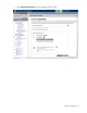
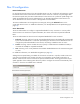
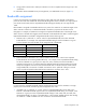
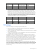
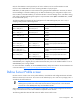
Table Of Contents
- HP Virtual Connect for c-Class BladeSystemVersion 3.01User Guide
- Notice
- Contents
- Introduction
- Overview
- HP Virtual Connect Manager
- Domain management
- Domain overview
- Firmware updates
- Domain Settings (Domain Configuration) screen
- Domain Settings (Domain IP Address) screen
- Domain Settings (Domain Enclosures) screen
- Domain Settings (Backup/Restore) screen
- Domain Settings (Local Users) screen
- Directory Settings (Directory Server) screen
- Directory Settings (Directory Groups) screen
- Directory Settings (Directory Certificate) screen
- Test LDAP authentication
- SNMP overview
- System Log screen
- System Log Configuration
- Network management
- Networks overview
- Define Ethernet Network screen
- Edit Ethernet Network screen
- Ethernet Networks (External Connections) screen
- Ethernet Networks (Server Connections) screen
- Ethernet Settings (MAC Addresses) screen
- Ethernet Settings (Port Monitoring) screen
- Ethernet Settings (Advanced Settings) screen
- Stacking Links screen
- Shared uplink sets and VLAN tagging
- Define Shared Uplink Set screen
- Shared Uplink Sets (External Connections) screen
- Shared Uplink Sets (Associated Networks) screen
- Storage management
- Server management
- Certificate Administration
- Hardware information screens
- Enclosure Information screen
- Enclosure Status screen
- Interconnect Bays Status and Summary screen
- Causes for INCOMPATIBLE status
- Interconnect Bay Summary screen (Ethernet module)
- Interconnect Bay Summary screen (VC-FC Module)
- Module removal and replacement
- Interconnect Bay Overall Status icon definitions
- Interconnect Bay OA Reported Status icon definitions
- Interconnect Bay VC Status icon definitions
- Interconnect Bay OA Communication Status icon definitions
- Server Bays Summary screen
- Server Bay Status screen
- Acronyms and abbreviations
- Glossary
- Index
Server management 97
The Allocated Bandwidth column displays "not allocated" until the profile is assigned to a device bay that
contains a server. At that time, bandwidth is allocated to each connection and the result is reported in this
column. See "Bandwidth assignment (on page 98)."
The Mapping column describes how each connection of a profile is assigned to physical devices in a
server, and to which interconnect bay that device is connected. The four FlexNICs on port 1 of a server
LOM that supports Flex-10 are numbered LOM:1-a, LOM:1-b, LOM:1-c, and LOM:1-d. If a LOM does not
support Flex-10, then it is simply referenced by its port number (for example, LOM:1 or LOM:2).
Port assignment
A server profile is simply a list of connections and other parameters until that profile is applied to a
physical server. The same profile can be mapped to server hardware differently depending on the
presence or absence of different mezzanine cards, and if Ethernet devices in the server are capable of
supporting Flex-10.
In versions of firmware prior to VC 2.00 (versions that do not support Flex-10), server profile connections
are assigned to a half-height server in the following order:
1. Assign a connection to LOM port 1.
2. Assign a connection to LOM port 2.
3. Assign a connection to MEZ1 port 1 (if present).
4. Assign a connection to MEZ1 port 2 (if present).
5. Assign a connection to MEZ2 port 1 (if present).
6. Assign a connection to MEZ2 port 2 (if present).
7. Assign a connection to MEZ2 port 3 (if present).
8. Assign a connection to MEZ2 port 4 (if present).
Connections are assigned to full-height servers in a similar way, but MEZ1 could have four ports and an
additional mezzanine slot (MEZ3) exists.
Virtual Connect v2.00 and higher implements the same assignment algorithm with the exception that the
algorithm repeats for all remaining unassigned profile connections. Additional profile connections can be
assigned to Flex-10 capable devices with a maximum of four connections per Flex-10 capable port.
For example, a profile with eight connections is assigned to a half-height server with a Flex-10 LOM and
a traditional NIC mezzanine in MEZ1 in the following order:
1. Assign profile connection 1 to LOM port 1.
2. Assign profile connection 2 to LOM port 2.
3. Assign profile connection 3 to MEZ1 port 1.
4. Assign profile connection 4 to MEZ1 port 2.
5. Assign profile connection 5 to LOM port 1 because it is Flex-10 capable and can support up to four
connections.
6. Assign profile connection 6 to LOM port 2 because it is Flex-10 capable and can support up to four
connections.
7. MEZ1 is not Flex-10 capable in this example, so additional connections cannot be assigned to
MEZ1. Therefore, assign profile connection 7 to LOM port 1 because it is Flex-10 capable and can
support up to four connections.