
Manual
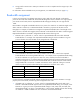
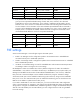
Table Of Contents
- HP Virtual Connect for c-Class BladeSystemVersion 3.01User Guide
- Notice
- Contents
- Introduction
- Overview
- HP Virtual Connect Manager
- Domain management
- Domain overview
- Firmware updates
- Domain Settings (Domain Configuration) screen
- Domain Settings (Domain IP Address) screen
- Domain Settings (Domain Enclosures) screen
- Domain Settings (Backup/Restore) screen
- Domain Settings (Local Users) screen
- Directory Settings (Directory Server) screen
- Directory Settings (Directory Groups) screen
- Directory Settings (Directory Certificate) screen
- Test LDAP authentication
- SNMP overview
- System Log screen
- System Log Configuration
- Network management
- Networks overview
- Define Ethernet Network screen
- Edit Ethernet Network screen
- Ethernet Networks (External Connections) screen
- Ethernet Networks (Server Connections) screen
- Ethernet Settings (MAC Addresses) screen
- Ethernet Settings (Port Monitoring) screen
- Ethernet Settings (Advanced Settings) screen
- Stacking Links screen
- Shared uplink sets and VLAN tagging
- Define Shared Uplink Set screen
- Shared Uplink Sets (External Connections) screen
- Shared Uplink Sets (Associated Networks) screen
- Storage management
- Server management
- Certificate Administration
- Hardware information screens
- Enclosure Information screen
- Enclosure Status screen
- Interconnect Bays Status and Summary screen
- Causes for INCOMPATIBLE status
- Interconnect Bay Summary screen (Ethernet module)
- Interconnect Bay Summary screen (VC-FC Module)
- Module removal and replacement
- Interconnect Bay Overall Status icon definitions
- Interconnect Bay OA Reported Status icon definitions
- Interconnect Bay VC Status icon definitions
- Interconnect Bay OA Communication Status icon definitions
- Server Bays Summary screen
- Server Bay Status screen
- Acronyms and abbreviations
- Glossary
- Index
Server management 94
“Bays 1-4 (HP Integrity BL890c i2)”. This is true in the left navigation tree, in the Server Bays summary
screen, in the list of bays that a profile can be assigned to in the Edit Server Profile screen, and so on.
A profile is assigned to an entire multi-blade server, not to the individual blades in the server. If a profile
is assigned to an auxiliary blade (for example, a profile is assigned to an empty bay and then a multi-
blade server is installed) that profile is ignored (in this case it’s the same as a profile assigned to a
covered bay). In such a case VCM identifies the bay that the profile is assigned to as “Covered –
Auxiliary”.
VCM maps the profile connection entries to ports on the blades in a multi-blade server as follows:
• Ethernet profile connection entries are evenly distributed across all of the blades in a multi-blade
server. For example, if a multi-blade server is comprised of 4 blades then the 1st, 5th, 9th, etc
Ethernet connections are assigned to the first blade, the 2nd, 6th, 10th etc Ethernet connections are
assigned to the second blade, and so forth. The mapping of connection entries to specific ports on a
blade are done the same way as for other full-height blades.
For more information, see "Port assignment (on page 97)."
• FC profile connection entries are mapped to blades such that all of the FC HBAs on the first blade
are mapped first, then the HBAs on the second blade, and so on. When a profile is first created it
will have enough FC profile connections for the HBAs on one blade. More FC connections can be
added only after the profile has been assigned to a multi-blade server. The maximum number of FC
connections allowed is N times the original number of entries where N is the number of blades in the
multi-blade server that a profile is assigned to.
There are rare situations where VCM will not be able to retrieve information about all of the blades in
multi-blade server (such as certain hardware failures that keep a blade from being in a normal state prior
to applying power). In such cases VCM displays the Major error status icon. Where text is shown with the
icon, the text is “Missing Data”. This is an indication of a serious problem with the multi-blade server that
needs to be fixed. VCM cannot properly map profile connections to a server when it is in this state.
Multi-blade servers do not support iSCSI or FCoE.
Flex-10 overview
Flex-10 technology is exclusive to Virtual Connect environments, and it allows Flex-10 enabled 10Gb
NICs to enumerate as four FlexNICs per 10Gb port. These FlexNICs are actual PCIe functions, and they
appear to the operating system or hypervisor as discrete NICs, each with its own driver instance.