
Manual


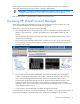
Table Of Contents
- HP Virtual Connect for c-Class BladeSystemVersion 3.01User Guide
- Notice
- Contents
- Introduction
- Overview
- HP Virtual Connect Manager
- Domain management
- Domain overview
- Firmware updates
- Domain Settings (Domain Configuration) screen
- Domain Settings (Domain IP Address) screen
- Domain Settings (Domain Enclosures) screen
- Domain Settings (Backup/Restore) screen
- Domain Settings (Local Users) screen
- Directory Settings (Directory Server) screen
- Directory Settings (Directory Groups) screen
- Directory Settings (Directory Certificate) screen
- Test LDAP authentication
- SNMP overview
- System Log screen
- System Log Configuration
- Network management
- Networks overview
- Define Ethernet Network screen
- Edit Ethernet Network screen
- Ethernet Networks (External Connections) screen
- Ethernet Networks (Server Connections) screen
- Ethernet Settings (MAC Addresses) screen
- Ethernet Settings (Port Monitoring) screen
- Ethernet Settings (Advanced Settings) screen
- Stacking Links screen
- Shared uplink sets and VLAN tagging
- Define Shared Uplink Set screen
- Shared Uplink Sets (External Connections) screen
- Shared Uplink Sets (Associated Networks) screen
- Storage management
- Server management
- Certificate Administration
- Hardware information screens
- Enclosure Information screen
- Enclosure Status screen
- Interconnect Bays Status and Summary screen
- Causes for INCOMPATIBLE status
- Interconnect Bay Summary screen (Ethernet module)
- Interconnect Bay Summary screen (VC-FC Module)
- Module removal and replacement
- Interconnect Bay Overall Status icon definitions
- Interconnect Bay OA Reported Status icon definitions
- Interconnect Bay VC Status icon definitions
- Interconnect Bay OA Communication Status icon definitions
- Server Bays Summary screen
- Server Bay Status screen
- Acronyms and abbreviations
- Glossary
- Index
Overview 8
By stacking (cabling) the Ethernet modules within the domain and connecting the FC modules to the same
set of FC SANs, every server blade in the domain can be configured to access any external network
connection. With this configuration, the administrator can use Virtual Connect Manager to deploy and
migrate a server blade profile to any server in the Virtual Connect domain without changing external LAN
or SAN configurations.
Using multiple enclosures
Multiple enclosure support enables up to four c7000 enclosures to be managed within a single Virtual
Connect domain for a total of 128 servers, if double-dense support is enabled. Multiple enclosure
domains are not supported on c3000 enclosures. The VC-Enet modules use stacking cables between
enclosures so that network traffic can be routed from any server Ethernet port to any uplink within the VC
domain.
By stacking (cabling) the Ethernet modules within the domain, every server blade in the domain can be
configured to access any external network connection. Fibre Channel modules within different enclosures
are each connected directly to the same set of FC SANs. With this configuration, the administrator can
use Virtual Connect Manager to deploy and migrate a server blade profile to any server in the Virtual
Connect domain without changing external LAN or SAN configurations.
Using multiple c7000 enclosures, you can install up to 16 VC-Enet modules and up to 16 VC-FC modules
in the same domain, with a maximum of 8 VC-Enet or 4 VC-FC modules per enclosure.
The management interfaces for all enclosure OAs and VC modules within the same VC domain must be
on the same lightly loaded subnet. The OA IP addresses used must be configured to be static.