
Manual
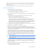
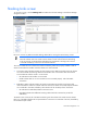
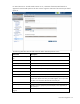
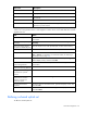
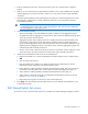
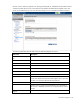


Table Of Contents
- HP Virtual Connect for c-Class BladeSystemVersion 3.01User Guide
- Notice
- Contents
- Introduction
- Overview
- HP Virtual Connect Manager
- Domain management
- Domain overview
- Firmware updates
- Domain Settings (Domain Configuration) screen
- Domain Settings (Domain IP Address) screen
- Domain Settings (Domain Enclosures) screen
- Domain Settings (Backup/Restore) screen
- Domain Settings (Local Users) screen
- Directory Settings (Directory Server) screen
- Directory Settings (Directory Groups) screen
- Directory Settings (Directory Certificate) screen
- Test LDAP authentication
- SNMP overview
- System Log screen
- System Log Configuration
- Network management
- Networks overview
- Define Ethernet Network screen
- Edit Ethernet Network screen
- Ethernet Networks (External Connections) screen
- Ethernet Networks (Server Connections) screen
- Ethernet Settings (MAC Addresses) screen
- Ethernet Settings (Port Monitoring) screen
- Ethernet Settings (Advanced Settings) screen
- Stacking Links screen
- Shared uplink sets and VLAN tagging
- Define Shared Uplink Set screen
- Shared Uplink Sets (External Connections) screen
- Shared Uplink Sets (Associated Networks) screen
- Storage management
- Server management
- Certificate Administration
- Hardware information screens
- Enclosure Information screen
- Enclosure Status screen
- Interconnect Bays Status and Summary screen
- Causes for INCOMPATIBLE status
- Interconnect Bay Summary screen (Ethernet module)
- Interconnect Bay Summary screen (VC-FC Module)
- Module removal and replacement
- Interconnect Bay Overall Status icon definitions
- Interconnect Bay OA Reported Status icon definitions
- Interconnect Bay VC Status icon definitions
- Interconnect Bay OA Communication Status icon definitions
- Server Bays Summary screen
- Server Bay Status screen
- Acronyms and abbreviations
- Glossary
- Index

Network management 77
1.
Enter the shared uplink set name. The uplink set name can be up to 64 characters in length (no
spaces).
2. Add one or more external ports using the Add Port pull-down menu. Only available ports are listed,
and they display the current port link status. Select two or more ports to ensure a high availability
connection.
3. Select the speed and duplex (where applicable) of the uplink ports. Click the drop-down box under
Speed/Duplex, and then select a setting. Half-duplex operation is not supported by the Virtual
Connect Ethernet module.
IMPORTANT: Be sure that the uplink interface port speed matches the speed set on the
corresponding network switch port. If using autonegotiation, both ports must be configured to
use autonegotiation or they might not link.
4. Select the Connection Mode:
o Auto (recommended)—This mode enables the uplinks to attempt to form aggregation groups
using IEEE 802.3ad link aggregation control protocol, and to select the highest performing uplink
as the active path to external networks.
Aggregation groups require multiple ports from a single Virtual Connect Ethernet module to be
connected to a single external switch that supports automatic formation of LACP aggregation
groups. Multiple aggregation groups may be formed from the ports selected for the network. The
highest performing aggregation group is selected as active, with other aggregation groups and
individual links used as standby connections.
o Failover—If this mode is selected, set the port to Primary or Secondary. Only a single link is used
as the active link to the external networks with other ports used as standby connections.
5. Identify the Associated Networks that will use this shared uplink:
a. Right-click the header row in the Associated Networks table to display a menu, and then select
Add.
b. Enter the name of the network.
c. Enter the number for the VLAN ID (1 to 4094) for that network as defined by the network
administrator and as configured on the external Ethernet switch.
d. Select whether to enable (checked) or disable (unchecked) native VLAN. Only one network can
be selected as the native VLAN. See "Shared uplink sets and VLAN tagging (on page 74)."
e. Select whether to enable (checked) or disable (unchecked) Smart Link (on page 53).
f. Select whether to designate (checked) or not designate (unchecked) the network as a private
network ("Private Networks" on page 53).
g. Repeat steps a through f for all networks to use the shared uplink set.
6. Click Apply. The shared uplink and associated networks are now defined and available for use in
creating server profiles.
Edit Shared Uplink Set screen
To access this screen, click the shared uplink set to be edited in the left VC Manager navigation window.