
Manual
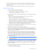
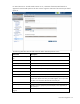
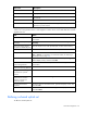
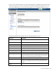


Table Of Contents
- HP Virtual Connect for c-Class BladeSystemVersion 3.01User Guide
- Notice
- Contents
- Introduction
- Overview
- HP Virtual Connect Manager
- Domain management
- Domain overview
- Firmware updates
- Domain Settings (Domain Configuration) screen
- Domain Settings (Domain IP Address) screen
- Domain Settings (Domain Enclosures) screen
- Domain Settings (Backup/Restore) screen
- Domain Settings (Local Users) screen
- Directory Settings (Directory Server) screen
- Directory Settings (Directory Groups) screen
- Directory Settings (Directory Certificate) screen
- Test LDAP authentication
- SNMP overview
- System Log screen
- System Log Configuration
- Network management
- Networks overview
- Define Ethernet Network screen
- Edit Ethernet Network screen
- Ethernet Networks (External Connections) screen
- Ethernet Networks (Server Connections) screen
- Ethernet Settings (MAC Addresses) screen
- Ethernet Settings (Port Monitoring) screen
- Ethernet Settings (Advanced Settings) screen
- Stacking Links screen
- Shared uplink sets and VLAN tagging
- Define Shared Uplink Set screen
- Shared Uplink Sets (External Connections) screen
- Shared Uplink Sets (Associated Networks) screen
- Storage management
- Server management
- Certificate Administration
- Hardware information screens
- Enclosure Information screen
- Enclosure Status screen
- Interconnect Bays Status and Summary screen
- Causes for INCOMPATIBLE status
- Interconnect Bay Summary screen (Ethernet module)
- Interconnect Bay Summary screen (VC-FC Module)
- Module removal and replacement
- Interconnect Bay Overall Status icon definitions
- Interconnect Bay OA Reported Status icon definitions
- Interconnect Bay VC Status icon definitions
- Interconnect Bay OA Communication Status icon definitions
- Server Bays Summary screen
- Server Bay Status screen
- Acronyms and abbreviations
- Glossary
- Index
Network management 75
For Virtual Connect v1.34 and Virtual Connect v2.10, a maximum of 64 associated networks is
supported in each shared uplink set. All other versions support a maximum of 32 networks per shared
uplink set.
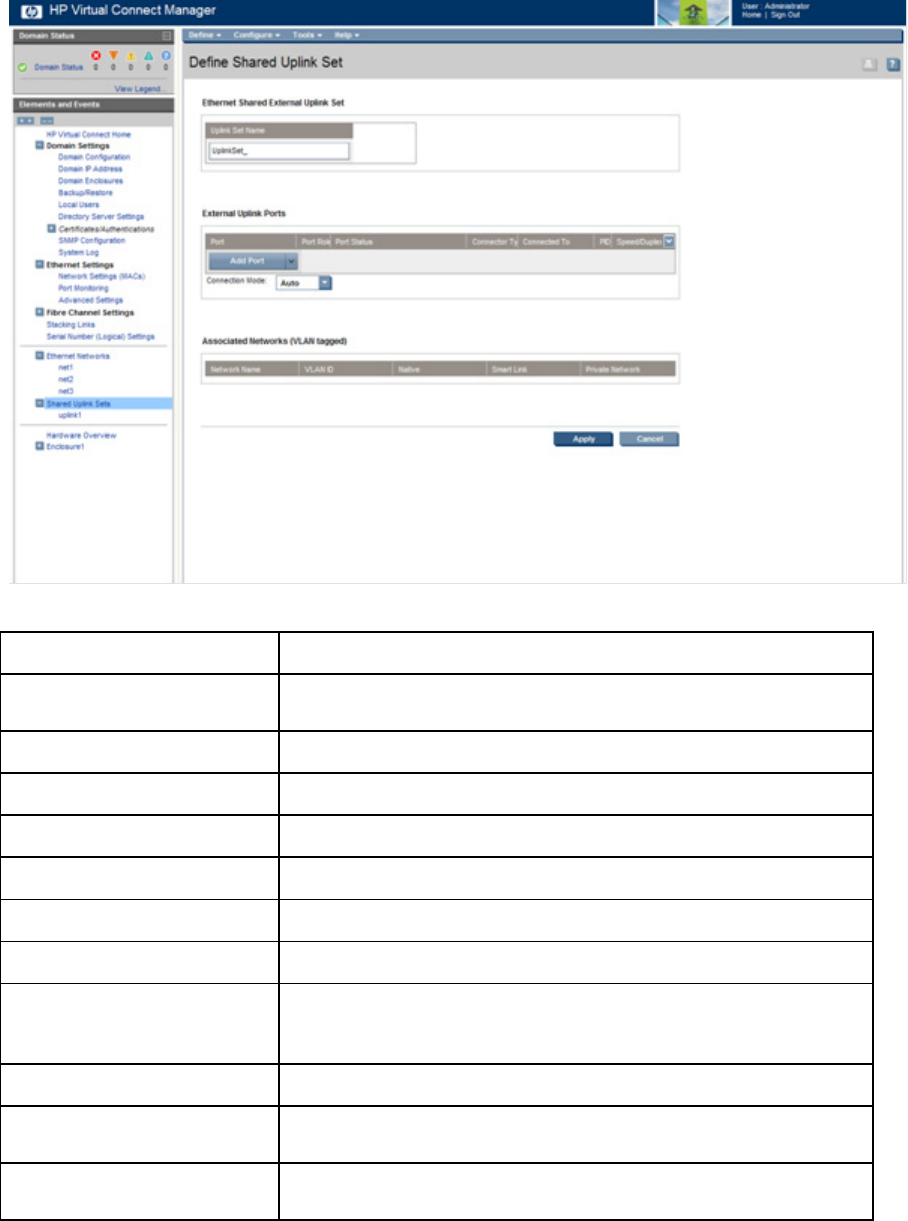
The following table describes the fields within the Define Shared Uplink Set screen.
Field name Description
Ethernet Shared External Uplink
Set
Uplink Set Name Descriptive name for the shared uplink set. Do not use spaces.
External Uplink Ports
Port Enclosure, bay, and port number
Port Role Displays whether the port is designated as primary or secondary
Port Status Displays linked or unlinked
Connector type The type of connector on the port; for example, RJ-45
Connected to
If the individual port is connected to a switch that supports LLDP, the
switch MAC address and switch port number appear. A link is provided
to obtain more information about the far-end switch port.
PID PID status icon (illuminated or not illuminated) for the port
Speed/Duplex
Pull-down menu to specify the speed and duplex (where applicable) of
the uplink port
Associated Networks (VLAN-
tagged)