
Manual
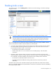
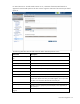
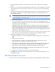


Table Of Contents
- HP Virtual Connect for c-Class BladeSystemVersion 3.01User Guide
- Notice
- Contents
- Introduction
- Overview
- HP Virtual Connect Manager
- Domain management
- Domain overview
- Firmware updates
- Domain Settings (Domain Configuration) screen
- Domain Settings (Domain IP Address) screen
- Domain Settings (Domain Enclosures) screen
- Domain Settings (Backup/Restore) screen
- Domain Settings (Local Users) screen
- Directory Settings (Directory Server) screen
- Directory Settings (Directory Groups) screen
- Directory Settings (Directory Certificate) screen
- Test LDAP authentication
- SNMP overview
- System Log screen
- System Log Configuration
- Network management
- Networks overview
- Define Ethernet Network screen
- Edit Ethernet Network screen
- Ethernet Networks (External Connections) screen
- Ethernet Networks (Server Connections) screen
- Ethernet Settings (MAC Addresses) screen
- Ethernet Settings (Port Monitoring) screen
- Ethernet Settings (Advanced Settings) screen
- Stacking Links screen
- Shared uplink sets and VLAN tagging
- Define Shared Uplink Set screen
- Shared Uplink Sets (External Connections) screen
- Shared Uplink Sets (Associated Networks) screen
- Storage management
- Server management
- Certificate Administration
- Hardware information screens
- Enclosure Information screen
- Enclosure Status screen
- Interconnect Bays Status and Summary screen
- Causes for INCOMPATIBLE status
- Interconnect Bay Summary screen (Ethernet module)
- Interconnect Bay Summary screen (VC-FC Module)
- Module removal and replacement
- Interconnect Bay Overall Status icon definitions
- Interconnect Bay OA Reported Status icon definitions
- Interconnect Bay VC Status icon definitions
- Interconnect Bay OA Communication Status icon definitions
- Server Bays Summary screen
- Server Bay Status screen
- Acronyms and abbreviations
- Glossary
- Index

Network management 74
Port X0 indicates the 10Gb port connected through the midplane of horizontally-adjacent VC-Enet
modules.
Ports X7 and X8 connect to the internal link between horizontally-adjacent Flex-10 enabled VC-Enet
modules.
NOTE: Virtual Connect does not support stacking for FC modules, so each VC-FC module
requires uplink connections to the external FC SAN environment.
For more information on connecting stacking links, and stacking links in a multi-enclosure environment,
see the HP Virtual Connect for c-Class BladeSystem Setup and Installation Guide.
Shared uplink sets and VLAN tagging
A shared uplink set is a way of identifying Virtual Connect Ethernet module uplinks that will carry multiple
networks over the same cable. In this case, each Ethernet packet carries a VLAN tag (IEEE 802.1Q) to
identify the specific network to which it belongs. On shared uplinks, the VLAN tags are added when
packets leave the VC-enabled enclosure and are removed when packets enter the enclosure. The external
Ethernet switch and the Virtual Connect Manager must be configured to use the same VLAN tag identifier
(a number between 1 and 4094) for each network on the shared uplink(s).
Virtual Connect places no special restrictions on which VLAN identifiers can be used, so the VLAN IDs
already used for the networks in the data center can be used on these shared uplinks. To configure a
shared uplink set for VLAN tagging, obtain a list of the network names and their VLAN IDs.
A shared uplink set enables multiple ports to be included to support port aggregation and link failover
with a consistent set of VLAN tags.
Because VLAN tags are added or removed when Ethernet packets leave or enter the VC-Enet shared
uplink, the VLAN tags have no relevance after the Ethernet packet enters the enclosure.
IMPORTANT: If you are deploying a server where VLAN tags will be used (added) on the
server itself, do not connect the server Ethernet port carrying VLAN-tagged traffic to a shared
uplink set.
Identifying an associated network as the native VLAN causes all untagged incoming Ethernet packets to
be placed onto this network. Only one associated network can be designated as the native VLAN. All out-
going Ethernet packets are VLAN tagged.
To enable native VLAN when defining a shared uplink set, select the box under Native. To enable or
disable native VLAN on an existing network, go to the Edit a Shared Uplink Set screen ("Edit Shared
Uplink Set screen" on page 77). Click on the edit icon, and then select or deselect the box under Native.
Define Shared Uplink Set screen
To access this screen, click the Shared Uplink Sets link in the left VC Manager navigation window, and
then click Define Uplink Set, or select Define Uplink Set from the Define pull-down menu.
The Define Shared Uplink Set screen is accessible to all users with network privileges by clicking the
Define a Shared Uplink link from the VC Manager home page or from the Define pull-down menu.