Manual
Table Of Contents
- HP Virtual Connect for c-Class BladeSystemVersion 3.01User Guide
- Notice
- Contents
- Introduction
- Overview
- HP Virtual Connect Manager
- Domain management
- Domain overview
- Firmware updates
- Domain Settings (Domain Configuration) screen
- Domain Settings (Domain IP Address) screen
- Domain Settings (Domain Enclosures) screen
- Domain Settings (Backup/Restore) screen
- Domain Settings (Local Users) screen
- Directory Settings (Directory Server) screen
- Directory Settings (Directory Groups) screen
- Directory Settings (Directory Certificate) screen
- Test LDAP authentication
- SNMP overview
- System Log screen
- System Log Configuration
- Network management
- Networks overview
- Define Ethernet Network screen
- Edit Ethernet Network screen
- Ethernet Networks (External Connections) screen
- Ethernet Networks (Server Connections) screen
- Ethernet Settings (MAC Addresses) screen
- Ethernet Settings (Port Monitoring) screen
- Ethernet Settings (Advanced Settings) screen
- Stacking Links screen
- Shared uplink sets and VLAN tagging
- Define Shared Uplink Set screen
- Shared Uplink Sets (External Connections) screen
- Shared Uplink Sets (Associated Networks) screen
- Storage management
- Server management
- Certificate Administration
- Hardware information screens
- Enclosure Information screen
- Enclosure Status screen
- Interconnect Bays Status and Summary screen
- Causes for INCOMPATIBLE status
- Interconnect Bay Summary screen (Ethernet module)
- Interconnect Bay Summary screen (VC-FC Module)
- Module removal and replacement
- Interconnect Bay Overall Status icon definitions
- Interconnect Bay OA Reported Status icon definitions
- Interconnect Bay VC Status icon definitions
- Interconnect Bay OA Communication Status icon definitions
- Server Bays Summary screen
- Server Bay Status screen
- Acronyms and abbreviations
- Glossary
- Index

Network management 70
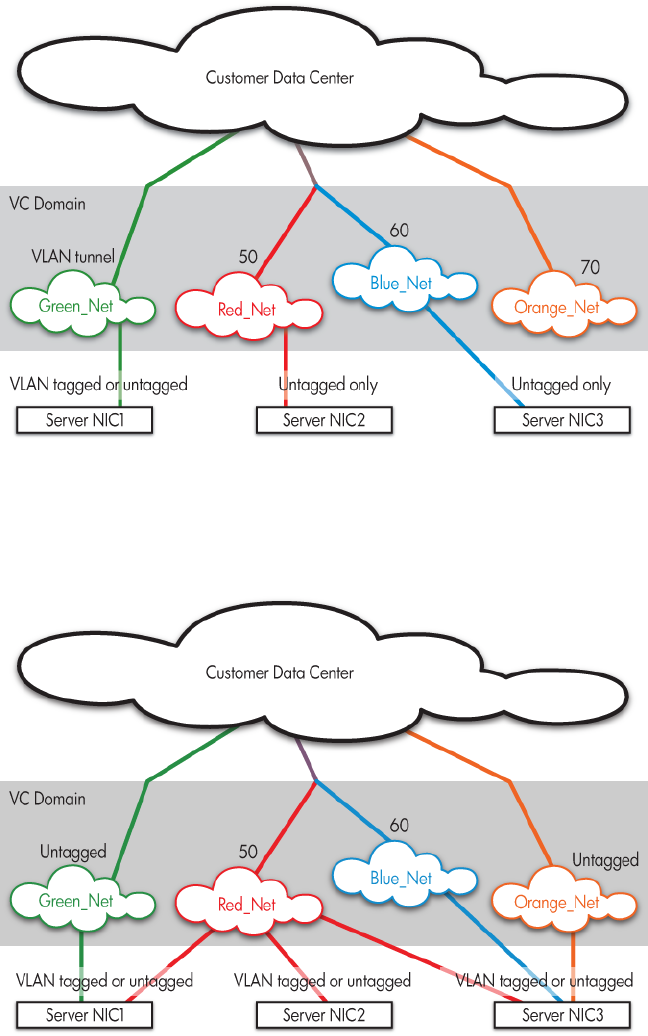
The following figure shows tunneled VLAN tags. On the dedicated, green network, both uplink and server
VLAN tags are tunneled through Virtual Connect unchanged. On the shared, red and blue networks,
uplink VLAN tags are mapped to networks. Untagged frames are mapped to the native VLAN, if present,
otherwise they are dropped. Server frames are untagged only, and tagged frames are dropped. Each
server port is connected to a single network.
The following figure shows mapped VLAN tags, a feature that enables users to define how each server
VLAN tag is mapped to a specific network. Each server port can connect to multiple networks. Server
NIC1 is connected to both the Green and Red networks. Server NIC2 is connected to the Red network,
and Server NIC3 is connected to the Red, Blue, and Orange networks. All server NICs can send and
received tagged or untagged traffic.
If Virtual Connect is set to map VLAN tags, VC-Enet modules accept incoming frames with valid server
VLAN tags and translate server-assigned VLANs into corresponding internal network VLANs, thus placing
the server packet on the correct network. When these frames reach the uplinks, network VLANs are once
again translated into external data center VLANs. Similarly, VLANs are translated back to server-assigned
VLANs (or stripped and untagged) before sending frames out to servers. This function allows for the


