
Manual
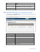
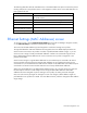
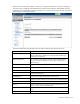
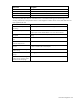
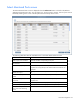

Table Of Contents
- HP Virtual Connect for c-Class BladeSystemVersion 3.01User Guide
- Notice
- Contents
- Introduction
- Overview
- HP Virtual Connect Manager
- Domain management
- Domain overview
- Firmware updates
- Domain Settings (Domain Configuration) screen
- Domain Settings (Domain IP Address) screen
- Domain Settings (Domain Enclosures) screen
- Domain Settings (Backup/Restore) screen
- Domain Settings (Local Users) screen
- Directory Settings (Directory Server) screen
- Directory Settings (Directory Groups) screen
- Directory Settings (Directory Certificate) screen
- Test LDAP authentication
- SNMP overview
- System Log screen
- System Log Configuration
- Network management
- Networks overview
- Define Ethernet Network screen
- Edit Ethernet Network screen
- Ethernet Networks (External Connections) screen
- Ethernet Networks (Server Connections) screen
- Ethernet Settings (MAC Addresses) screen
- Ethernet Settings (Port Monitoring) screen
- Ethernet Settings (Advanced Settings) screen
- Stacking Links screen
- Shared uplink sets and VLAN tagging
- Define Shared Uplink Set screen
- Shared Uplink Sets (External Connections) screen
- Shared Uplink Sets (Associated Networks) screen
- Storage management
- Server management
- Certificate Administration
- Hardware information screens
- Enclosure Information screen
- Enclosure Status screen
- Interconnect Bays Status and Summary screen
- Causes for INCOMPATIBLE status
- Interconnect Bay Summary screen (Ethernet module)
- Interconnect Bay Summary screen (VC-FC Module)
- Module removal and replacement
- Interconnect Bay Overall Status icon definitions
- Interconnect Bay OA Reported Status icon definitions
- Interconnect Bay VC Status icon definitions
- Interconnect Bay OA Communication Status icon definitions
- Server Bays Summary screen
- Server Bay Status screen
- Acronyms and abbreviations
- Glossary
- Index
Network management 65
Whenever port monitoring is enabled, a warning icon appears in the banner at the top of the page. If
port monitoring is configured and enabled within the Virtual Connect domain, Ethernet data from the
monitored ports is replicated on the network analyzer port, which poses a security risk and could result in
network loops if not connected properly.
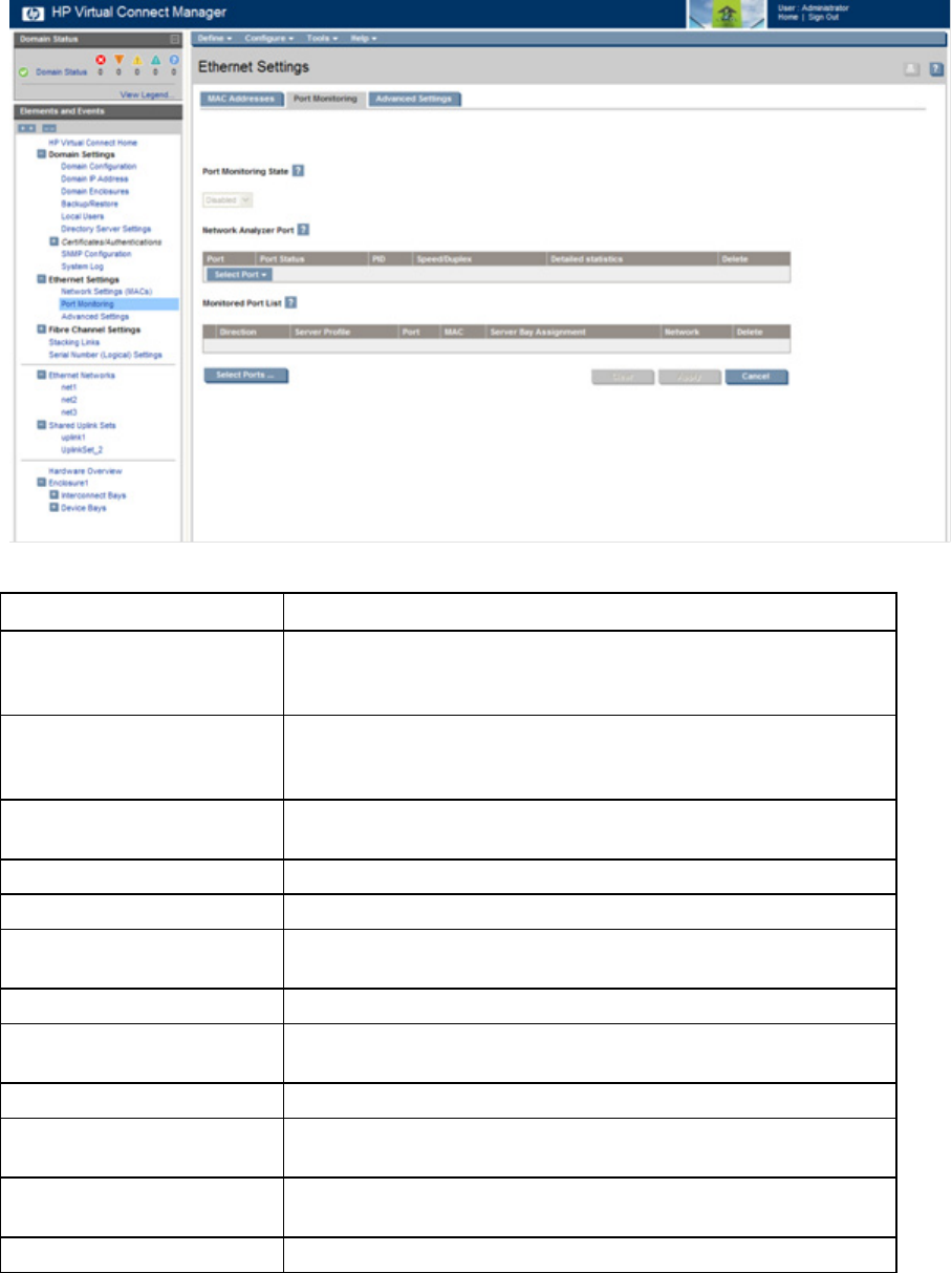
The following table describes the fields within the Ethernet Settings (Port Monitoring) screen.
Field name Description
Port Monitoring State
Used to enable or disable port monitoring. This feature allows the
network administrator to disable port monitoring while maintaining the
monitored port configuration.
Network Analyzer Port
This is the port to which all monitored traffic is directed. After selection,
this port is no longer available for use in any other Virtual Connect
Ethernet network.
Port
Identifies the enclosure, bay, and port number of the network analyzer
port.
Port Status Displays link status of the network analyzer port
PID PID status icon (lit or unlit) for the network analyzer port
Speed/Duplex
Pull-down menu to specify the speed and duplex (where applicable) of
the network analyzer port
Detailed statistics Click the link to display detailed statistics about this port
Delete
Displays Delete icon. Click to remove the network analyzer port. To
change the network analyzer port, the current port must first be deleted.
Monitored Port List Displays up to 16 server ports that are monitored at the same time.
Direction
Direction of traffic on the port being monitored. Valid choices are From
Server, To Server, or Both. The default is Both.
Server Profile
Identifies the server profile associated with the monitored port if one
exists.
Port Enclosure, bay, and port number of monitored port