
Manual
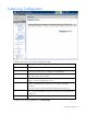
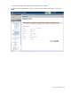
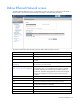
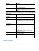
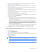

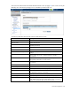
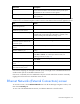
Table Of Contents
- HP Virtual Connect for c-Class BladeSystemVersion 3.01User Guide
- Notice
- Contents
- Introduction
- Overview
- HP Virtual Connect Manager
- Domain management
- Domain overview
- Firmware updates
- Domain Settings (Domain Configuration) screen
- Domain Settings (Domain IP Address) screen
- Domain Settings (Domain Enclosures) screen
- Domain Settings (Backup/Restore) screen
- Domain Settings (Local Users) screen
- Directory Settings (Directory Server) screen
- Directory Settings (Directory Groups) screen
- Directory Settings (Directory Certificate) screen
- Test LDAP authentication
- SNMP overview
- System Log screen
- System Log Configuration
- Network management
- Networks overview
- Define Ethernet Network screen
- Edit Ethernet Network screen
- Ethernet Networks (External Connections) screen
- Ethernet Networks (Server Connections) screen
- Ethernet Settings (MAC Addresses) screen
- Ethernet Settings (Port Monitoring) screen
- Ethernet Settings (Advanced Settings) screen
- Stacking Links screen
- Shared uplink sets and VLAN tagging
- Define Shared Uplink Set screen
- Shared Uplink Sets (External Connections) screen
- Shared Uplink Sets (Associated Networks) screen
- Storage management
- Server management
- Certificate Administration
- Hardware information screens
- Enclosure Information screen
- Enclosure Status screen
- Interconnect Bays Status and Summary screen
- Causes for INCOMPATIBLE status
- Interconnect Bay Summary screen (Ethernet module)
- Interconnect Bay Summary screen (VC-FC Module)
- Module removal and replacement
- Interconnect Bay Overall Status icon definitions
- Interconnect Bay OA Reported Status icon definitions
- Interconnect Bay VC Status icon definitions
- Interconnect Bay OA Communication Status icon definitions
- Server Bays Summary screen
- Server Bay Status screen
- Acronyms and abbreviations
- Glossary
- Index
Network management 58
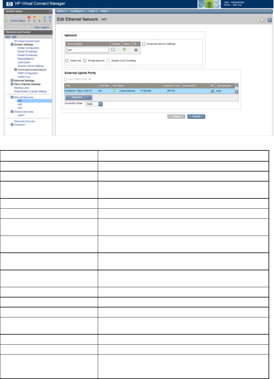
This screen has similar fields to the Define Ethernet Network screen (on page 54). This screen can only be
edited by users with network privileges, but it is viewable by all authorized users.
The following table describes the fields within the Edit Network screen.
Field name Description
Network
Network Name Name of the network
Enabled
Displays the current state of the network as enabled (checked) or
disabled (unchecked)
Status Displays the current status of the network
PID PID status for the overall network
Advanced Network Settings
If checked, displays additional selections for advanced network
settings
Smart Link
Shows whether Smart Link is enabled (checked) or disabled
(unchecked)
Private Network
Shows whether this network is designated (checked) or not
designated (unchecked) as a private network
Enable VLAN Tunneling
Shows whether VLAN tunneling is enabled (checked) or disabled
(unchecked)
External Uplink Ports
Use Shared Uplink Set Enables selection or creation of a shared uplink set
Port Network port locations (enclosure, bay, and port numbers)
Port Role
Applicable when Failover Connection Mode is selected. The port can
be designated as Primary or Secondary.
Port Status Displays the current linked status of the selected port
Connector Type Displays the type of connector on the port; for example, RJ-45
Connected to
If the port is connected to a switch that supports LLDP, the switch
MAC address and switch port number appear. A link is provided to
obtain more information about the far-end switch port.