
Manual
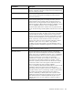

Table Of Contents
- HP Virtual Connect for c-Class BladeSystemVersion 3.01User Guide
- Notice
- Contents
- Introduction
- Overview
- HP Virtual Connect Manager
- Domain management
- Domain overview
- Firmware updates
- Domain Settings (Domain Configuration) screen
- Domain Settings (Domain IP Address) screen
- Domain Settings (Domain Enclosures) screen
- Domain Settings (Backup/Restore) screen
- Domain Settings (Local Users) screen
- Directory Settings (Directory Server) screen
- Directory Settings (Directory Groups) screen
- Directory Settings (Directory Certificate) screen
- Test LDAP authentication
- SNMP overview
- System Log screen
- System Log Configuration
- Network management
- Networks overview
- Define Ethernet Network screen
- Edit Ethernet Network screen
- Ethernet Networks (External Connections) screen
- Ethernet Networks (Server Connections) screen
- Ethernet Settings (MAC Addresses) screen
- Ethernet Settings (Port Monitoring) screen
- Ethernet Settings (Advanced Settings) screen
- Stacking Links screen
- Shared uplink sets and VLAN tagging
- Define Shared Uplink Set screen
- Shared Uplink Sets (External Connections) screen
- Shared Uplink Sets (Associated Networks) screen
- Storage management
- Server management
- Certificate Administration
- Hardware information screens
- Enclosure Information screen
- Enclosure Status screen
- Interconnect Bays Status and Summary screen
- Causes for INCOMPATIBLE status
- Interconnect Bay Summary screen (Ethernet module)
- Interconnect Bay Summary screen (VC-FC Module)
- Module removal and replacement
- Interconnect Bay Overall Status icon definitions
- Interconnect Bay OA Reported Status icon definitions
- Interconnect Bay VC Status icon definitions
- Interconnect Bay OA Communication Status icon definitions
- Server Bays Summary screen
- Server Bay Status screen
- Acronyms and abbreviations
- Glossary
- Index

Hardware information screens 134
Port Statistic Description
EtherStatsPkts1024to1518Octets
The total number of packets (including bad packets) received that were
between 1024 and 1518 octets in length inclusive (excluding framing
bits, but including FCS octets).
EtherStatsOversizePkts
The total number of packets received that were longer than 1518
octets (excluding framing bits, but including FCS octets) and were
otherwise well-formed.
EtherStatsJabbers
The total number of packets received that were longer than 1518
octets (excluding framing bits, but including FCS octets), and had
either a bad FCS with an integral number of octets (FCS Error) or a
bad FCS with a non-integral number of octets (Alignment Error). This
definition of jabber is different than the definition in IEEE-802.3 section
8.2.1.5 (10BASE5) and section 10.3.1.4 (10BASE2). These
documents define jabber as the condition where any packet exceeds
20 ms. The allowed range to detect jabber is between 20 ms and 150
ms.
EtherStatsOctets
The total number of octets of data (including those in bad packets)
received on the FCS octets). This object can be used as a reasonable
estimate of Ethernet utilization. If greater precision is required, the
StatsPkts and StatsOctets objects should be sampled before and after a
common interval. The differences in the sampled values are Pkts and
Octets, respectively, and the number of seconds in the interval is
Interval. These values are used to calculate the Utilization as follows:
Utilization = [(Pkts * (9.6 + 6.4) + (Octets * .8)) / (Interval *
10,000)]. The result of this equation is the value Utilization which is
the percent utilization of the Ethernet segment on a scale of 0 to 100
percent.
EtherStatsPkts
The total number of packets (including bad packets, broadcast
packets, and multicast packets) received.
EtherStatsCollisions
The best estimate of the total number of collisions on this Ethernet
segment. The value returned depends on the location of the RMON
probe. Section 8.2.1.3 (10BASE-5) and section 10.3.1.3 (10BASE-2)
of IEEE standard 802.3 states that a station must detect a collision, in
the receive mode, if three or more stations are transmitting
simultaneously. A repeater port must detect a collision when two or
more stations are transmitting simultaneously. Therefore, a probe
placed on a repeater port could record more collisions than a probe
connected to a station on the same segment would. Probe location
plays a much smaller role when considering 10BASE-T.
14.2.1.4 (10BASE-T) of IEEE standard 802.3 defines a collision as the
simultaneous presence of signals on the DO and RD circuits
(transmitting and receiving at the same time). A 10BASE-T station can
only detect collisions when it is transmitting. Therefore, probes placed
on a station and a repeater should report the same number of
collisions. Additionally, an RMON probe inside a repeater should
ideally report collisions between the repeater and one or more other
hosts (transmit collisions as defined by IEEE 802.3k) plus receiver
collisions observed on any coax segments to which the repeater is
connected.