
Manual

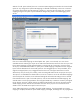
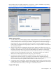
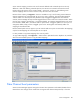
Table Of Contents
- HP Virtual Connect for c-Class BladeSystemVersion 3.01User Guide
- Notice
- Contents
- Introduction
- Overview
- HP Virtual Connect Manager
- Domain management
- Domain overview
- Firmware updates
- Domain Settings (Domain Configuration) screen
- Domain Settings (Domain IP Address) screen
- Domain Settings (Domain Enclosures) screen
- Domain Settings (Backup/Restore) screen
- Domain Settings (Local Users) screen
- Directory Settings (Directory Server) screen
- Directory Settings (Directory Groups) screen
- Directory Settings (Directory Certificate) screen
- Test LDAP authentication
- SNMP overview
- System Log screen
- System Log Configuration
- Network management
- Networks overview
- Define Ethernet Network screen
- Edit Ethernet Network screen
- Ethernet Networks (External Connections) screen
- Ethernet Networks (Server Connections) screen
- Ethernet Settings (MAC Addresses) screen
- Ethernet Settings (Port Monitoring) screen
- Ethernet Settings (Advanced Settings) screen
- Stacking Links screen
- Shared uplink sets and VLAN tagging
- Define Shared Uplink Set screen
- Shared Uplink Sets (External Connections) screen
- Shared Uplink Sets (Associated Networks) screen
- Storage management
- Server management
- Certificate Administration
- Hardware information screens
- Enclosure Information screen
- Enclosure Status screen
- Interconnect Bays Status and Summary screen
- Causes for INCOMPATIBLE status
- Interconnect Bay Summary screen (Ethernet module)
- Interconnect Bay Summary screen (VC-FC Module)
- Module removal and replacement
- Interconnect Bay Overall Status icon definitions
- Interconnect Bay OA Reported Status icon definitions
- Interconnect Bay VC Status icon definitions
- Interconnect Bay OA Communication Status icon definitions
- Server Bays Summary screen
- Server Bay Status screen
- Acronyms and abbreviations
- Glossary
- Index

Server management 107
Server network mapping is similar to the set of networks defined under a shared uplink set. The only
difference is that when defining a shared uplink set, the networks are created in the Virtual Connect
Domain along with options such as "Native VLAN", "Smart Link", and so on, while defining server
network mappings does not result in creation of any networks in the VC Domain.
Because of this similarity, a Copy From… button is available to copy a set of existing external VLAN to
network mappings from a shared uplink set into a server port's mappings. The network designated as
"Native VLAN" in a shared uplink set by default accepts untagged or tagged frames from external
switches, but VC Manager always transmits tagged frames from this vNet out to external switches. When
used as server mapping, this behavior is reversed. By default, VC transmits untagged frames to the server
from the Native VLAN, that is, the Native VLAN is copied as the "untagged" option for a server port. To
change this default, simply set the "untagged" option to be "Unassigned" and manually add a new
mapping for the Native VLAN.
Because shared uplink sets can support up to 32 networks and server ports are restricted to 28 mappings,
only the first 28 mappings of a shared uplink set are copied.
It is also possible to copy VLAN mappings from a server profile.
To copy VLAN mappings, click Copy From.... Select Profile or UplinkSet from the dropdown list, and then
select from the available options to copy the VLAN mappings.
Fibre Channel boot parameters
Virtual Connect Manager supports setting Fibre Channel boot parameters and enable/disable of Fibre
Channel boot. This change can be made when running the Fibre Channel Setup Wizard, or from the