
Manual
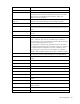

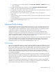
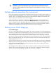
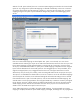
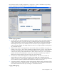
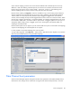
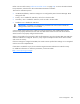
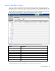
Table Of Contents
- HP Virtual Connect for c-Class BladeSystemVersion 3.01User Guide
- Notice
- Contents
- Introduction
- Overview
- HP Virtual Connect Manager
- Domain management
- Domain overview
- Firmware updates
- Domain Settings (Domain Configuration) screen
- Domain Settings (Domain IP Address) screen
- Domain Settings (Domain Enclosures) screen
- Domain Settings (Backup/Restore) screen
- Domain Settings (Local Users) screen
- Directory Settings (Directory Server) screen
- Directory Settings (Directory Groups) screen
- Directory Settings (Directory Certificate) screen
- Test LDAP authentication
- SNMP overview
- System Log screen
- System Log Configuration
- Network management
- Networks overview
- Define Ethernet Network screen
- Edit Ethernet Network screen
- Ethernet Networks (External Connections) screen
- Ethernet Networks (Server Connections) screen
- Ethernet Settings (MAC Addresses) screen
- Ethernet Settings (Port Monitoring) screen
- Ethernet Settings (Advanced Settings) screen
- Stacking Links screen
- Shared uplink sets and VLAN tagging
- Define Shared Uplink Set screen
- Shared Uplink Sets (External Connections) screen
- Shared Uplink Sets (Associated Networks) screen
- Storage management
- Server management
- Certificate Administration
- Hardware information screens
- Enclosure Information screen
- Enclosure Status screen
- Interconnect Bays Status and Summary screen
- Causes for INCOMPATIBLE status
- Interconnect Bay Summary screen (Ethernet module)
- Interconnect Bay Summary screen (VC-FC Module)
- Module removal and replacement
- Interconnect Bay Overall Status icon definitions
- Interconnect Bay OA Reported Status icon definitions
- Interconnect Bay VC Status icon definitions
- Interconnect Bay OA Communication Status icon definitions
- Server Bays Summary screen
- Server Bay Status screen
- Acronyms and abbreviations
- Glossary
- Index
Server management 102
Column name Description
Model Model name of the server blade in the device bay
Status Status of the server blade in the device bay
UID Icon indicates if the server blade UID is on or off
If VC-assigned MAC addresses, WWNs, or non-default Fibre Channel boot parameters are being used,
always power off the affected server blades before assigning a profile. When assigning a VC-assigned
serial number (logical), power off the server. To power off a server blade, see "Server Bay status screen
(on page 150)."
To define a server profile:
1. Enter the server profile name.
The server profile name can be up to 64 characters in length (no spaces). Because the server profile
can be assigned to different locations, HP recommends that the name reflect the server function. The
profile can be renamed at any time.
2. To user server factory defaults for Ethernet MAC addresses, Fibre Channel WWNs, or serial
numbers (logical), select the Advanced Profile Settings checkbox. For more information, see
"Advanced Profile Settings (on page 103)."
3. Set up Ethernet Network Connections for ports 1 and 2. For each port, do the following:
a. To select an available Ethernet network, click the down arrow in the Network Name field.
b. Select a network from the previously defined networks.
You can also select multiple networks. For more information, see "Multiple network connections
for a server port (on page 104)."
c. Change the port speed setting:
i. Click the drop-down arrow in the Port Speed Setting Column.
ii. Select Preferred, Auto, or Custom. If Custom is selected, set the port speed, and then click
OK.
d. To override the current PXE settings on the server, click the down arrow under PXE and select
Disabled or Enabled.
Only one port can have PXE enabled by Virtual Connect on a server blade. However, if the
default 'Use BIOS' setting is selected, the server uses the current settings in the BIOS. On
mezzanine cards only, the 'Use BIOS' selection can allow more than one NIC port to have PXE
enabled. Only one embedded NIC can have PXE enabled.
The MAC field indicates whether the profile uses a server factory default or a VC-defined MAC
address. VC-defined MAC addresses are not assigned until the profile is created.
PXE allows an Ethernet port to be used for a network boot. PXE should only be enabled on a port
that is connected to a network with a properly configured PXE environment.
4. If the server will use more than two network connections, right-click in the Ethernet Network
Connections table to display a menu, and then select Add.
5. Set up the Fibre Channel connections. Two Fibre Channel connections exist for each set of
horizontally adjacent interconnect bays in the enclosure that contain VC-FC modules. For each port,
do the following:
a. Click the down arrow under FC SAN Name to select an available SAN.