HP L2401x and x2401 LED Backlit Monitors User Guide
© 2012, Hewlett-Packard Development Company, L.P. The only warranties for HP products and services are set forth in the express warranty statements accompanying such products and services. Nothing herein should be construed as constituting an additional warranty. HP shall not be liable for technical or editorial errors or omissions contained herein. This document contains proprietary information that is protected by copyright.
About This Guide This guide provides information on setting up the monitor, installing the VESA adapter plate, contacting HP support, and technical specifications. WARNING! Text set off in this manner indicates that failure to follow directions could result in bodily harm or loss of life. CAUTION: Text set off in this manner indicates that failure to follow directions could result in damage to equipment or loss of information. NOTE: Text set off in this manner provides important supplemental information.
iv About This Guide
Table of contents 1 Product Features ............................................................................................................... 1 HP LED Backlit Monitors ............................................................................................................ 1 2 Setting Up the Monitor ...................................................................................................... 2 Extending the Monitor Stand ....................................................................
vi
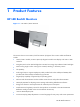
1 Product Features HP LED Backlit Monitors Figure 1-1 HP L2401x/x2401 Monitors The monitors have an active matrix, thin-film transistor (TFT) panel. The monitor models and features include: ● L2401x/x2401 models, 60.
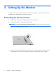
2 Setting Up the Monitor To set up the monitor, ensure that the power is turned off to the monitor, computer system, and other attached devices, and then follow the instructions below. Extending the Monitor Stand 1. Lift the monitor from its box and place it face down on a flat surface. 2. Grasp the stand and pull upward until fully extended. CAUTION: Do not touch the surface of the panel. Pressure on the panel may cause permanent non-uniformity of color or disorientation of the liquid crystals.
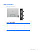
Side connectors Figure 2-2 Side connectors Table 2-1 Side connectors Connector Function 1 DisplayPort Connects the DisplayPort video cable (provided with select models) from the computer to the monitor 2 HDMI Connects the HDMI video cable (provided with select models) from the computer to the monitor 3 DC Power Jack Connects the external power adapter to the monitor Side connectors 3
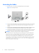
Connecting the Cables 1. Place the monitor in a convenient, well-ventilated location near the computer. Figure 2-3 Connecting the monitor 2. Connect one end of the DisplayPort signal cable (provided with select models) to the DisplayPort connector on the side of the monitor and the other end to the DisplayPort connector on the computer. 3.
Front Panel Controls Figure 2-4 Monitor front panel controls Table 2-2 Monitor front panel controls Control 1 Function Power LED Blue = Fully powered. Amber = Sleep mode. Off = Off mode. 2 Power Turns the monitor on or off. 3 Menu Opens, selects or exits the OSD menu. 4 Minus Moves the OSD cursor down/decreases the OSD adjustment level. 5 Plus Moves the OSD cursor up/increases the OSD adjustment level. 6 OK If the OSD menu is on, press to select the highlighted menu item.
Adjusting the Tilt Tilt the monitor's panel to set it to a comfortable eye level. Figure 2-5 Tilting the monitor VESA Adapter Plate The monitor includes a VESA 100 mm x 100 mm (3.9 in x 3.9 in) adapter plate. This can be used to attach the monitor panel to a VESA-compatible device (purchased separately), such as a stand, swing arm, or other mounting fixture.
Safety Information This product has not been evaluated for connection to an “IT” power system (an AC distribution system with no direct connection to the earth, according to IEC 60950). WARNING! Always disconnect the monitor from the power source before lifting, moving, or removing the stand from your monitor. Failure to do so can result in personal injury or equipment damage. Removing the Stand from the Monitor To avoid injury and equipment damage, always complete the following steps in order: 1.
5. Remove the four screws from the monitor stand. Figure 2-7 Removing the screws from the monitor stand Save the monitor stand and the four screws, in the event that you decide to convert your monitor back to a desktop monitor in the future.
Installing the VESA Adapter Plate onto the Monitor NOTE: This apparatus is intended to be supported by a UL or CSA Listed wall-mount bracket. 1. Remove the stand from the monitor panel. Refer to Removing the Stand from the Monitor on page 7. 2. Install the VESA adapter plate that shipped with the monitor. a. With the monitor face down on the table, slide the VESA adapter plate from the lower edge of the monitor toward the bracket hinge until the VESA adapter plate is in position over the bracket hinge.
b. Secure the lower edge of the VESA adapter plate to the bracket hinge with four screws. Figure 2-9 Securing the VESA adapter plate 3. To attach the monitor to a VESA-compatible device (purchased separately), follow the instructions included with that device to ensure that the monitor is safely attached. CAUTION: This monitor supports the VESA industry-standard 100 mm mounting holes. To attach a third-party solution to the monitor, four 4 mm, 0.
4. Remove the four screws securing the lower edge of the VESA adapter plate to the bracket hinge. Figure 2-10 Removing the screws securing the VESA adapter plate 5. Slide the VESA adapter plate toward the lower edge of the monitor and off the bracket hinge.
Replacing the Stand 1. Align the monitor stand over the bracket hinge and secure it with the four screws. Figure 2-12 Securing the monitor stand 2. Attach the hinge cover.
Turning on the Monitor 1. Press the power button on the front of the monitor to turn it on. 2. Press the power button on the computer to turn it on. CAUTION: Burn-in image damage may occur on monitors that display the same static image on the screen for a prolonged period of time (12 or more consecutive hours of non-use). To avoid burn-in image damage on the monitor screen, you should always activate a screen saver application or turn off the monitor when it is not in use for a prolonged period of time.
3 Finding More Information Refer to the HP LCD Monitors Reference Guide included on the CD with your monitor for additional information on: ● Optimizing monitor performance ● Safety and maintenance guidelines ● Installing software from the CD ● Using the OSD menu ● Downloading software from the Web ● Agency regulatory information ● Troubleshooting and recommended solutions to common problems For information on theft deterrence, refer to the HP Display Assistant User Guide included on the CD t
A Technical Specifications NOTE: All specifications represent the typical specifications provided by HP component manufacturers; actual performance may vary either higher or lower. L2401x/x2401 Models Table A-1 L2401x/x2401 Specifications Display 60.96 cm 24 in Type MVA (Multi-domain Vertical Alignment Viewable Image Size 60.96 cm diagonal Tilt 10° to 35° Maximum Weight (Unpacked) 3.3 kg 7.32 lbs Height 43.13 cm 16.98 inches Width 56.69 cm 22.32 inches Depth 13.09 cm 5.
Table A-1 L2401x/x2401 Specifications (continued) Altitude: Operating 0 to 5,000 m 0 to 16,400 ft Storage 0 to 12,192 m 0 to 40,000 ft Measured Power Consumption: Full Power 28 W Typical Settings 23 W Sleep <0.5 W Switch Off <0.
Table A-2 Factory Preset Modes (continued) Preset Pixel Format Horz Freq (kHz) Vert Freq (Hz) 15 1680 × 1050 65.29 59.954 16 1920 × 1080 67.50 60.00 Energy-saver Feature The monitors support a reduced power state. The reduced power state will be entered into if the monitor detects the absence of either the horizontal sync signal and/or the vertical sync signal.