HP LD4201, LD4210 and LD4710 Digital Signage Displays User Guide
© 2010, 2011 Hewlett-Packard Development Company, L.P. The information contained herein is subject to change without notice. The only warranties for HP products and services are set forth in the express warranty statements accompanying such products and services. Nothing herein should be construed as constituting an additional warranty. HP shall not be liable for technical or editorial errors or omissions contained herein. This document contains proprietary information that is protected by copyright.
About this guide This guide provides information on setting up the display, installing drivers, using the On-Screen Display menu, troubleshooting, and technical specifications. WARNING! Text set off in this manner indicates that failure to follow directions could result in bodily harm or loss of life. CAUTION: Text set off in this manner indicates that failure to follow directions could result in damage to equipment or loss of information.
iv About this guide ENWW
Table of contents 1 Product features ............................................................................................................... 1 HP Digital Signage models ........................................................................................................ 1 Accessories ............................................................................................................................. 1 Optional accessories ...................................................................
Downloading from the Web ..................................................................................... 29 Using the auto-adjustment function (RGB INPUT source only) ........................................................ 30 Using the On-Screen Display menu ........................................................................................... 30 Using the remote control to adjust the OSD ................................................................ 31 OSD menu selections ....................
Transmission/Receiving Protocol .............................................................................................. 59 01. Power (Command: a) ......................................................................................... 59 02. Input Select (Command: b) (Main Picture Input) ..................................................... 61 03. Aspect Ratio (Command: c) (Main picture format) ................................................. 62 04. Screen Mute (Command: d) ........................
41. Power On Delay (Command: f h) ........................................................................ 85 42. Language (Command: f i) ................................................................................... 85 43. DPM Select (Command: f j) ................................................................................ 86 44. Reset (Command: f k) ........................................................................................ 86 45. Energy saving (Command: f I) .......................
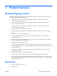
1 Product features HP Digital Signage models The HP LCD digital signage displays have a wide-aspect active matrix thin-film transistor (TFT) panel. The displays features include the following: ● HP LD4201 model, 106.7 cm (42-inch diagonal) widescreen viewable area display with 1920 x 1080 native resolution ● HP LD4210 model, 106.7 cm (42-inch diagonal) widescreen viewable area display with 1920 x 1080 native resolution ● HP LD4710 model, 119.
● Power cord ● DisplayPort cable ● HDMI cable ● RGB (VGA) cable Optional accessories Optional accessories (purchased separately) might vary depending on the model.
2 Safety and maintenance guidelines Important safety information A power cord is included with the display. If another cord is used, use only a power source and connection appropriate for this display. For information on the correct power cord set to use with the display, refer to the Power cord set requirements on page 95. WARNING! To reduce the risk of electric shock or damage to the equipment: • Do not disable the power cord grounding feature. The grounding plug is an important safety feature.
Maintenance guidelines To enhance the performance and extend the life of the display: ● Do not open the display cabinet or attempt to service this product yourself. Adjust only those controls that are covered in the operating instructions. If the display is not operating properly or has been dropped or damaged, contact an authorized HP dealer, reseller, or service provider. ● Use only a power source and connection appropriate for this display, as indicated on the label/ back plate of the display.
Cleaning the display 1. Turn off the display and unplug the power cord from the back of the unit. 2. Dust the display by wiping the screen and the cabinet with a soft, clean antistatic cloth. 3. For more difficult cleaning situations, use a 50/50 mix of water and Isopropyl alcohol. CAUTION: Spray the cleaner onto a cloth and use the damp cloth to gently wipe the screen surface. Never spray the cleaner directly on the screen surface. It might seep behind the bezel and damage the electronics.
3 Setting up the display To set up the display, ensure that the power is turned off to the display, media player/computer system, and other attached devices, and then follow the instructions below. Installing the stand (sold separately) 1. Take the parts for the stand out of the box. ● HP LD4201 and LD4210—Four screws M4 x 32 mm (1.26 in) and stand Figure 3-1 HP LD4201 and LD4210—Stand accessory contents ● HP LD4710—Four screws M4 x 10 mm (0.
2. Place a soft cloth on the table and place the display with the screen facing downward. Connect the stand as shown in the following figure.
3. Use the screws to secure the stand on the rear side of the product as shown in the figure.
Connecting the speakers (sold separately) 1. Mount the speakers onto the display. Figure 3-7 Mounting the speakers 2. Use the four Taptite D3 x 12 mm (0.47 in) screws to secure the speakers to the display.
3. After installing the speakers, use the cable holders and cable ties (available on select models) to secure the speaker cables.
4. After installing the speakers, connect to the SPEAKER input terminal by connecting the proper color match for the left and right speakers. Figure 3-11 Connecting to the input terminal Rotating to the portrait position When installing the display in the portrait position, rotate it clockwise based on its front. The display can be rotated in only one direction. NOTE: The display cannot be rotated if it is installed on the stand.
Using the remote control Inserting the batteries 1. Slide off the battery cover. 2. Insert the batteries with correct polarity (+/-). 3. Close the battery cover. NOTE: To prevent environmental pollution, dispose of used batteries in accordance with your local recycling guidelines.
Identifying remote control buttons Figure 3-14 Remote control buttons 1 2 14 INPUT ENERGY MONITOR 15 OFF ON SAVING 3 4 5 6 7 8 MARK ARC PSM P BRIGHT A NESS G 18 E MUTE MENU 9 10 11 16 17 AUTO USB 19 20 OK BACK TILE EXIT ID 12 ON OFF 21 22 13 Component Function 1 Power on/off Turns the display on from standby or off to standby 2 MONITOR ON or OFF Turns the display on and off 3 Number Types numbers 4 ENWW Not supported 5 Volume up (+) or down (-) Adjusts the vo
Component Function 10 OK Accepts a selection or displays the current mode 11 BACK Navigates one step back in an interactive application 12 ID ON or OFF Enables the display lock 13 USB menu control buttons Use with the HP Media Sign Player option lists in the USB menu 14 ENERGY SAVING Adjusts the Energy Saving mode 15 INPUT Opens the Input Source menu options (RGB, HDMI/DVI, and DisplayPort) 16 Not supported 17 ARC Selects the Aspect Ratio converter mode 18 BRIGHTNESS Adjusts the r
Identifying display components The components of the display and their functions are identified in the following sections.
Display control panel Figure 3-17 HP LD4201 and HP LD4210—Display control panel 1 2 3 4 5 6 7 8 Figure 3-18 HP LD4710—Display control panel 1 2 3 4 5 6 7 8 Component Function 1 Power ON/OFF Press to turn the power ON. Press again to turn it OFF. 2 AUTO/SET When the OSD window is closed, the auto-adjustment feature to optimize the screen image is activated. When the OSD window is open, press to select a menu item or save changes.
Display ports Figure 3-19 Display ports Component Function 1 Power cord receptacle Power cord receptacle to connect the display to an electrical outlet. 2 RS-232-C (Control) serial ports RS-232-C (Control) serial ports connect to RS-232 devices. 3 HDMI/DVI, RGB IN, and RGB OUT HDMI supports High Definition (HD) input and HDCP (High-bandwidth Digital Content Protection). Some devices require HDCP in order to display HD signals.
Security cable provision—To help prevent theft, a security cable provision is available on the rear of the display. The cable and lock required to connect to the display are available separately and can be purchased from HP.
Connecting to external devices 1. Be sure that the display, media player/computer, and all attached devices are turned off. 2. Connect the signal input cable. For additional information, refer to one of the following signal input cable sections: 3.
4. Connect the AC power cord to the AC-IN connector on the rear of the display and the other end to an electrical outlet. Before connecting the power cord, please read the power-cord safety precautions in the Important safety information on page 3.
5. Turn on power to the display by pressing the power button (1). Figure 3-24 HP LD4201 and HP LD4210—Power button 1 Figure 3-25 HP LD4710—Power button 1 6. Turn on the media player/computer. 7. Select an input signal: Press the INPUT button on the remote control to open the Input List, select the appropriate input signal, and then press the OK button to save your change.
Connecting RGB 1. For analog operation, connect the D-Sub signal cable to the RGB IN (1) connector on the rear of the display and the other end to the connector (2) on the media player/computer. NOTE: If connecting to a Mac media player/computer, use the standard Mac adapter (3)–not included. Figure 3-26 Connecting the D-Sub signal cable 2 1 3 2.
Connecting DisplayPort (480p/576p/720p/1080i/1080p) 1. Connect the DisplayPort cable to the DP IN port on the display and to the DisplayPort OUT port on the media player/computer, and then connect the display power cord. Figure 3-28 Connecting DisplayPort input to a media player/computer 2. Select an input signal. Press the INPUT button on the remote control, select the DP input signal, and then press the OK button to save.
● Connect an HDMI to DVI signal cable to the HDMI/DVI port on the display, and then to the DVI port on the media player/computer. For AUDIO input from the media player/computer (this is only needed with DVI input signal connections), connect the RCA-PC audio cable (cable not included) to the display and to the Audio OUT ports on the media player/computer, then connect the display power cord.
Connecting LAN (HP LD4210 and HP LD4710 only) The LAN input on the display can connect to a media player/computer, a router (switch), or an Intranet. A LAN connection with the display establishes communication between your media player/ computer and the display.
Connecting daisy chain displays Multiple displays (up to 25) can be connected in a daisy chain (connect several displays together in Tile Mode) to a computer using DisplayPort IN/OUT or with the combination of RGB IN/OUT and RS-232-C IN/OUT ports on the display. To connect displays in a daisy chain, the displays must all be connected with the same input/output source (DisplayPort IN/OUT, RS-232-C IN/OUT, or RGB IN/OUT) as shown in the figures below.
Figure 3-34 Daisy chain connection—RS-232-C RS-232C RS-232C RS-232C RS-232C (CONTROL) (CONTROL) (CONTROL) (CONTROL) OUT OUT OUT OUT IN IN IN IN 2 3 4 1 ENWW Connecting daisy chain displays 27
4 Operating the display Software and utilities HP displays are Plug-and-Play with Windows® XP, Windows Vista™, and Windows 7 operating systems, so you do not need to download the .INF file or the .ICM file for these operating systems. The most current versions of the following software and utilities can be downloaded from the following HP website for use with the displays as needed: www.hp.com. ● Auto-adjustment Pattern Utility—Optimizes the display.
Installing the .INF and .ICM files You can install the .INF and .ICM files from the CD or download them from the HP displays support website. Installing from the CD To install the .INF and .ICM files on the media player/computer from the CD: 1. Insert the CD in the media player/computer CD-ROM drive. The CD menu appears. 2. View the Display Driver Readme file. 3. Select Install display driver software. 4. Follow the on-screen instructions. 5.
Using the auto-adjustment function (RGB INPUT source only) You can optimize the screen performance by using the AUTO/SET button on the display (AUTO button on the remote control) and the Auto-adjustment Pattern Utility software on the CD provided. NOTE: Do not use this procedure if the display is set to use a DisplayPort or HDMI/DVI input source.
Icon Main menu Function description Tile Set or change the tile options USB Set or change the USB options Using the remote control to adjust the OSD Use the OSD to adjust the screen image based on your viewing preferences. To access the OSD, do the following: ENWW 1. If the display is not already on, press the power button to turn on the display. 2. Press the MENU button (1) on the remote control. 3. To access a control, use the down arrow ▼ or up arrow ▲ button (2). 4.
OSD menu selections The following table lists the On-Screen Display (OSD) menu selections and their functional descriptions. Icon Main menu Submenu Description PICTURE Aspect Ratio Selects from the following screen image sizes: Energy Saving Picture Mode 32 Chapter 4 Operating the display ● 16:9—Widescreen mode. ● 1:1—Picture format is 1:1 aspect ratio. ● Just Scan—Allows you to enjoy the transmitted data fully without any images cut off.
Icon Main menu Submenu Description ◦ Color—Adjusts the color to desired level. ◦ Tint—Adjusts the tint to a desired level. NOTE: If the Picture Mode setting is set to Vivid, Standard, Cinema, Sport, or Game, the above adjustments will be automatically set to predefined settings. Advanced Control Select from the following screen color adjustment settings: ● ◦ Cool—Slightly purplish white. ◦ Medium—Slightly bluish white. ◦ Warm—Slightly reddish white.
Icon Main menu AUDIO Submenu Description Expert 1 and Expert 2 Control Select from the following settings: ● Dynamic Contrast—Optimizes the contrast automatically according to the brightness of the reflection. ● Noise Reduction—Removes the noise up to the point where it does not damage the original picture. ● Gamma—Set your own gamma value. On the display, high gamma values display whitish images and low gamma values display high contrast images.
Icon Main menu Submenu Description Speaker Adjusts internal speaker status (speakers sold separately). To use this feature, select On; to turn off the feature, select Off. To use an external hi-fi stereo system, turn off the internal speakers of the display. TIME OPTION ENWW DisplayPort Audio Out Select DisplayPort or Analog. Clock Resets the Day, Hour, and Minute if the current time is incorrect. On Time The on time automatically switches the display on at the pre-set time.
Icon Main menu Submenu Description Network Setup Select the method of assigning an IP address to the display. IP Mode options: ● DHCP—Allows the display IP Address to be assigned automatically when the display is attached to the network through a router. ● Manual—Allows you to assign the IP Address, Subnet Mask, Gateway, and DNS Server. See your network administrator for the correct manual entries to enter.
Icon Main menu Submenu Description Movie List Play movie files on a USB storage device. Lock System Enables the USB security function to prevent the playing of unauthorized files from a USB storage device with the HP Media Sign Player. Set Password Allows you to set a password for the HP Media Sign Player. NOTE: All USB menu options are disabled until a correct password is entered.
Clock The Clock menu allows you to reset the clock manually if the current time is incorrect. 1. Press the MENU button, and then use the down arrow ▼ or up arrow ▲ button to select the TIME menu. 2. Press the right arrow ► button, and then use the down arrow ▼ or up arrow ▲ button to select the Clock menu. 3. Press the right arrow ► button, and then use the down arrow ▼ or up arrow ▲ button to set the hour (00h–23h). 4.
NOTE: In the event of a power interruption (disconnection or power failure), the Sleep Timer clock must be reset. Auto Off To set the display to switch to the off mode automatically after 15 minutes if Auto Off is active and there is no input signal: 1. Press the MENU button, and then use the down arrow ▼ or up arrow ▲ button to select the TIME menu. 2. Press the right arrow ► button, and then use the down arrow ▼ or up arrow ▲ button to select the Auto Off menu. 3.
Using ISM Method Displaying a static image on the screen for a prolonged period of time could result in burn-in or image sticking. To avoid burn-in or image sticking or to fix a ghost or burned-in image, do not display a fixed image for prolonged periods of time. Either turn the display off or change the image. If you display a static image for long periods of time, you can help to avoid ghost images or burn-in by using the ISM option as follows: 1.
Each display must be connected to every other display, using either RGB IN/RGB OUT or DP IN/ DP OUT as shown in the following figure. If you want to issue display commands from the media player/computer, you must connect each display with RS-232-C IN/RS-232-C OUT just like the video connections.
5 Using the HP Media Sign Player When you insert a USB storage device into the USB port in the back of the display, the Enter Password dialog box appears if you have the Lock System option turned ON. After entering your password, the HP Media Sign Player options appear with Photo List, Music List, and Movie List.
Options on full-sized photo view ● Slideshow—Starts the HP Media Sign Player. Only the files marked or selected are played unless there are no files marked, and then all files in the selected folder play in the order they appear in the Photo List. Set the time interval for all of the slides in the slide show in the Options dialog box. ● BGM (Background Music)—The HP Media Sign Player plays audio files while showing the selected images from the Photo List.
Music selection and menu options: The Play ►, Pause II, Stop ■, Reverse ◄◄, and Forward ►► buttons on the remote control are also available to use when playing music. ● Play—Starts the HP Media Sign Player. After Play is highlighted and OK is pressed, the selected music titles are played in the order that they are listed in the music list. If no music titles are selected, the player will play all the titles in the folder in the order they are listed in the Music List.
● Maximum FPS (frame per second) can be reached only at SD level. FPS is 25 FPS (720*576) or 30 FPS (720*480) depending on Resolution. ● Files more than 25 FPS or 30 FPS or higher might not be played properly. ● A video file name and its subtitle file name must be identical for it to be displayed. ● Playing a video via a USB connection that does not support high speed might not work properly. ● USB storage devices below USB 2.
A Troubleshooting Solving common problems The following table lists possible problems, the possible cause of each problem, and the recommended solutions. Problem Possible cause Solution No image is displayed. Power cord is not connected. Be sure the power cord is properly connected to the outlet. ● Verify that the outlet has power to it. ● Check that the fuse or breaker has not tripped or burned out. See if the power switch is turned on. Might need service.
Problem Possible cause Solution Key Lock On message appears when pressing the Menu button. Key Lock function is turned on. The control locking function prevents unintentional OSD setting changes. To unlock the controls, simultaneously press the Menu button and right arrow ► button for several seconds. (You cannot set this function using the remote control buttons. You can set this function with the display only.) The screen looks abnormal; screen position is wrong. Screen is out of adjustment.
Problem Possible cause Solution Black spots appear on the screen. Black spots are characteristics of the LCD panel. Several pixels (red, green, white, or black color) might appear on the screen, which can be attributable to the unique characteristics of the LCD panel. It is not a malfunction of the LCD. The power is suddenly turned off. Sleep timer setting is turned on, or power is interrupted. Check that the sleep timer is set. Check the power control settings.
B Technical specifications NOTE: All performance specifications are provided by the component manufacturers. Performance specifications represent the highest specification of all HP's component manufacturers' typical level specifications for performance; actual performance might vary either higher or lower. HP Digital Signage Display Table B-1 Specifications HP LD4201 HP LD4210 HP LD4710 Size 106.73 cm (42 in) 106.73 cm (42 in) 119.
Table B-1 Specifications (continued) Power consumption Resolution— maximum HP LD4201 HP LD4210 HP LD4710 On mode 220 W Typical 220 W Typical 270 W Typical Sleep mode ≤ 1 W (RGB) / 2 W (HDMI/ DVI) ≤ 1 W (RGB) / 2 W (HDMI/ DVI) ≤ 1 W (RGB) / 2 W (HDMI/ DVI) ≤ 1 W (RGB) / 2 W (DisplayPort) ≤ 1 W (RGB) / 2 W (DisplayPort) ≤ 1 W (RGB) / 2 W (DisplayPort) (if LAN OFF is selected) (if LAN OFF is selected) RGB 1920 x 1080 @ 60 Hz 1920 x 1080 @ 60 Hz 1920 x 1080 @ 60 Hz HDMI/DVI 1920 x 1080 @
Table B-1 Specifications (continued) Audio (select models) HP LD4201 HP LD4210 HP LD4710 RMS audio output 10 W + 10 W (R + L) 10 W + 10 W (R + L) 10 W + 10 W (R + L) Input sensitivity 0.7 Vrms 0.7 Vrms 0.7 Vrms Speaker impedance 8 Ohms 8 Ohms 8 Ohms HP LD4201 and HP LD4210 dimensions (with optional stand and speakers) Figure B-1 HP LD4201 and HP LD4210—Front and side view 121 mm (4.76 in) 933.2 mm (36.74 in) 67.4 mm (2.65 in) 16.9 mm (.66 in) 69.6 mm (2.74in) ENWW 75.2 mm (2.
Figure B-2 HP LD4201 and HP LD4210—Back view 855.1 mm (33.66 in) 400 mm (15.75 in) 113.9 mm (4.48 in) 600 mm (23.62 in) 52 Appendix B Technical specifications 332 mm (13.07 in) 56 mm (2.
HP LD4710 dimensions (with optional stand and speakers) Figure B-3 HP LD4710—Front and side view 122.9 mm (4.84 in) 72.9 mm (2.87 in) 94.3 mm (3.71 in) 1043.7 mm (41.09 in) 129.2 mm (5.09 in) 17.9 mm (.70 in) 1079.5 mm (42.5 in) 86.9 mm (3.42 in) 588.7 mm (23.18 in) 73.1 mm (2.88 in) 17.9 mm (.70 in) 624.6 mm (24.59 in) 17.9 mm (.70 in) 111 mm (4.37 in) 114.4 mm (4.50 in) 298.3 mm (11.74 in) Figure B-4 HP LD4710—Back view 962 mm (37.87 in) 800 mm (31.50 in) 400 mm (15.75 in) 332 mm (13.
Recognizing preset display resolutions The display resolutions listed below are the most commonly used modes and are set as factory defaults. This display automatically recognizes these preset modes and they will appear properly sized and centered on the screen. Preset display modes Table B-2 Factory preset display modes Preset Pixel format Horizontal frequency (kHz) Vertical Frequency (Hz) 1 720 x 400 31.468 70.1 *2 640 x 480 31.469 59.94 3 640 x 480 37.5 75 *4 800 x 600 37.879 60.
HDMI/DVI (DTV) DisplayPort 1080i o o 1080p o o NOTE: DTV/PC selection on HDMI/DVI inputs is available for media player/computer resolutions— 640 x 480/60 Hz, 1280 x 720/60 Hz, 1920 x 1080/60 Hz and DTV resolutions—480p, 720p, 1080p.
C Command reference Use this method to connect several products to a single PC. You can control several products at a time by connecting them to a single PC. If the Set ID menu in Option is set to OFF, the monitor ID value should be set between 1 and 99. Connecting the cable Connect the RS-232-C cable as shown in the following illustration. The RS-232-C protocol is used for communication between the media player/computer and the display.
Communication parameter ● Baud Rate—9600 baud rate (UART) ● Data Length—8 bit ● Parity Bit—None ● Stop Bit—1 bit ● Flow Control—None ● Communication Code—ASCII code ● Use a crossed (reverse) cable Command reference list ENWW COMMAND 1 COMMAND 2 DATA1 01. Power k a 00H–01H 02. Input Select k b 07H–0BH 03. Aspect Ratio k c 01H–1FH 04. Screen Mute k d 00H–01H 05. Volume Mute k e 00H–01H 06. Volume Control k f 00H–64H 07. Contrast k g 00H–64H 08.
COMMAND 1 COMMAND 2 DATA1 DATA2 DATA3 22. Tile V Position d f 00H–14H 23. Tile H Size d g 00H–64H 24. Tile V Size d h 00H–64H 25. Tile ID Set d i 00H–19H 26. Natural Mode (In Tile Mode) d j 00H–01H 27. Picture Mode (PSM) d x 00H–06H 28. Sound Mode d y 01H–05H 29. Fan Fault Check d w FFH 30. Elapsed Time Return d l FFH 31. Temperature Value d n FFH 32. Lamp Fault Check d p FFH 33. Auto Volume d u 00H–01H 34. Speaker d v 00H–01H 35.
Transmission/Receiving Protocol Transmission [Command1][Command2][][Set ID][][Data][Cr] *[Command 1] First command (k, j, m, d, f, x) *[Command 2] Second command (a to z) *[Set ID] Set up the Set ID number of product. range: 01H to 63H. by setting '0', server can control all products. When operating with more than 2 sets using set ID as '0' at the same time, do not check the ack message. Because all sets will send the ack message, it is not possible to check all of the ack messages.
[Data] 0: Power Off 1: Power On Acknowledgement [a][][Set ID][][OK][Data][x] To show the status of Power On/Off.
02. Input Select (Command: b) (Main Picture Input) To select input source for the Set. You can also select an input source using the INPUT button on the remote control.
03. Aspect Ratio (Command: c) (Main picture format) To adjust the screen format. You can also adjust the screen format using the ARC (Aspect Ratio Control) button on remote control or in the Screen menu.
[d][][Set ID][][OK][Data][x] 05. Volume Mute (Command: e) To control On/Off of the Volume Mute. Transmission [k][e][][Set ID][][Data][Cr] [Data] 0: Volume Mute On (Volume Off) 1: Volume Mute Off (Volume On) Acknowledgement [e][][Set ID][][OK][Data][x] [Data] 0: Volume Mute On (Volume Off) 1: Volume Mute Off (Volume On) 06. Volume Control (Command: f) To adjust Volume.
Real data mapping 0: Step 0 : A: Step 10 : F: Step 15 10: Step 16 : 64: Step 100 07. Contrast (Command: g) To adjust screen contrast. You can also adjust the contrast in the Picture menu.
08. Brightness (Command: h) To adjust screen brightness. You can also adjust the brightness in the Picture menu. Transmission [k][h][][Set ID][][Data][Cr] [Data] Min: 00H to Max: 64H Refer to “Real data mapping” as shown below. Acknowledgement [h][][Set ID][][OK][Data][x] Real data mapping 0: Step 0 : A: Step 10 : F: Step 15 10: Step 16 : 64: Step 100 09. Color (Command: i) (Video Timing only) To adjust the screen color. You can also adjust the color in the Picture menu.
Real data mapping 0: Step 0 : A: Step 10 : F: Step 15 10: Step 16 : 64: Step 100 Acknowledgement [i][][Set ID][][OK][Data][x] [Data] Min: 00H to Max: 64H (Hexadecimal code) 10. Tint (Command: j) (Video Timing only) To adjust the screen tint. You can also adjust the tint in the Picture menu.
Real data mapping 0: Step 0 : A: Step 10 : F: Step 15 10: Step 16 : 64: Step 100 Acknowledgement [j][][Set ID][][OK][Data][x] [Data] Red: 00H to Green: 64H Tint real data mapping 0: Step 0 to Red : 64: Step 100 to Green 11. Sharpness (Command: k) (Video Timing only) To adjust the screen Sharpness. You can also adjust the sharpness in the Picture menu.
Real data mapping 0: Step 0 : A: Step 10 : F: Step 15 10: Step 16 : 64: Step 100 Acknowledgement [k][][Set ID][][OK][Data][x] [Data] Min: 00H to Max: 64H 12. OSD Select (Command: l) To control OSD on/off to the set. Transmission [k][l][][Set ID][][Data][Cr] [Data] 0: OSD Off 1: OSD On Acknowledgement [l][][Set ID][][OK][Data][x] [Data] 0: OSD Off 1: OSD On 13. Remote Lock/Key Lock (Command: m) To control Remote Lock on/off to the set.
This function, when controlling RS-232C, locks the remote control and the local keys. Transmission [k][m][][Set ID][][Data][Cr] [Data] 0: Off 1: On Acknowledgement [m][][Set ID][][OK][Data][x] [Data] 0: Off 1: On 14. Balance (Command: t) To adjust the sound balance.
Balance: L50 to R50 15. Color Temperature (Command: u) To adjust the screen color temperature. Transmission [k][u][][Set ID][][Data][Cr] [Data] 0: Medium 1: Cool 2: Warm Acknowledgement [u][][Set ID][][OK][Data][x] [Data] 0: Medium 1: Cool 2: Warm 16. Abnormal state (Command: z) Abnormal State: Used to Read the power off status when Stand-by mode.
[Data] 0: Normal (Power on and signal exist) 1: No signal (Power on) 2: Turn the display off by remote control 3: Turn the display off by sleep time function 4: Turn the display off by RS-232-C function 8: Turn the display off by off time function 9: Turn the display off by auto off function 17. ISM Method (Command: j p) Used to select the afterimage preventing function.
[u][][Set ID][][OK][Data][x] 19. Key (Command: m c) To send IR remote key code. Transmission [m][c][][Set ID][][Data][Cr] Data Key code: Refer to the IR Codes Table on page 90 section. Acknowledgement [c][][Set ID][][OK][Data][x] 20. Tile Mode (Command: d d) Change a Tile Mode. Transmission [d][d][][Set ID][][Data][x] [Data] Description 00 or 11 Tile mode is off. 12 1 x 2 mode (column x row) 13 1 x 3 mode 14 1 x 4 mode ... ... 55 5 x 5 mode The [Data] cannot be set to 0X or X0 except 00.
Transmission [d][e][][Set ID][][Data][x] [Data] Min: 00H to Max: 14H 00H: Step -10 (Left) 14H: Step 10 (Right) Acknowledgement [e][][Set ID][][OK/NG][Data][x] 22. Tile V Position (Command: d f) To set the Vertical position. Transmission [d][f][][Set ID][][Data][x] [Data] Min: 00H to Max: 14H 00H: Step -10 (Left) 14H: Step 10 (Right) Acknowledgement [f][][Set ID][][OK/NG][Data][x] 23. Tile H Size (Command: d g) To set the Horizontal size.
Real data mapping 0: Step 0 : A: Step 10 : F: Step 15 10: Step 16 : 64: Step 100 Acknowledgement [g][][Set ID][][OK/NG][Data][x] 24. Tile V Size (Command: d h) To set the Vertical size.
25. Tile ID Set (Command: d i) To assign the Tile ID for Tiling function. Transmission [d][i][][Set ID][][Data][x] [Data] Min: 00H to Max: 19H (Hexadecimal code) Acknowledgement [i][][Set ID][][OK/NG][Data][x] 26. Natural Mode (In Tile Mode) (Command: d j) To assign the Title Natural mode for Tiling function.
27. Picture Mode (Command: d x) To adjust the picture mode. Transmission [d][x][][Set ID][][Data][x] Data Structure Data (Hex) MODE 00 Vivid 01 Standard 02 Cinema 03 Sport 04 Game 05 Expert 1 06 Expert 2 Acknowledgement [x][][Set ID][][OK/NG][Data][x] 28. Sound Mode (Command: d y ) To adjust the Sound mode.
Data (Hex) MODE 04 Sport 05 Game Acknowledgement [y][][Set ID][][OK/NG][Data][x] 29. Fan Fault check (Command: d w ) To check the Fan fault of the display. Transmission [d][w][][Set ID][][Data][x] [Data] Data is always FF (in Hex) Data ff: Read Status Acknowledgement [w][][Set ID][][OK/NG][Data][x] [Data] [Data] is the status value of the Fan fault. 0: Fan fault 1: Fan OK 2: N/A (Not Available) 30. Elapsed time return (Command: d l) To read the elapsed time.
[Data] Data is always FF (in Hex) Acknowledgement [l][][Set ID][][OK/NG][Data][x] [Data] The data means used hours. (Hexadecimal code) 31. Temperature value (Command: d n) To read the inside temperature value. Transmission [d][n][][Set ID][][Data][x] [Data] Data is always FF (in Hex) Acknowledgement [n][][Set ID][][OK/NG][Data][x] [Data] The data is 1 byte long in Hexadecimal. 32. Lamp fault Check (Command: d p) To check lamp fault.
[p][][Set ID][][OK/NG][Data][x] [Data] 0: Lamp Fault 1: Lamp OK 2: N/A(DPM/Power Off) 33. Auto volume (Command: d u) Automatically adjust the volume level. Transmission [d][u][][Set ID][][Data][x] [Data] 0: Off 1: On Acknowledgement [u][][Set ID][][OK/NG][Data][x] 34. Speaker (Command: d v) Turn the speaker on or off.
35. Time (Command: f a) Set the current time. Transmission [f][a][][Set ID][][Data1][][Data2][][Data3][Cr] [Data1] 0: Monday 1: Tuesday 2: Wednesday 3: Thursday 4: Friday 5: Saturday 6: Sunday [Data2] 00H to 17H (Hours) [Data3] 00H to 3BH (Minutes) Acknowledgement [a][][Set ID][][OK/NG][Data1][Data2][Data3][x] When reading data, FFH is inputted for [Data1], [Data2] and [Data3]. In other cases, all are treated as NG. 36. On Timer (On/Off Timer) Time (Command: f d) Set On Timer.
[Data1] 1. 2. 3.
37. Off Timer (On/Off Timer) Time (Command: f e) Set Off Timer. Transmission [f][e][][Set ID][][Data1][][Data2][][Data3][Cr] [Data1] 1. 2. 3.
Acknowledgement [e][][Set ID][][OK][Data1][Data2][Data3][x] 38. Scheduling Input select (Command: f u) (Main Picture Input) To select input source for TV depending on day.
39. Sleep Time (Command: f f) Set Sleep Time. Transmission [f][f][][Set ID][][Data][Cr] [Data] 0: Off 1: 10 2: 20 3: 30 4: 60 5: 90 6: 120 7: 180 8: 240 Acknowledgement [f][][Set ID][][OK/NG][Data][x] 40. Auto Off (Command: f g) Set Auto Sleep.
41. Power On Delay (Command: f h) Set the schedule delay when the power is turned on (Unit: second). Transmission [f][h][][Set ID][][Data][Cr] [Data] 00H to 64H (Data value) Real data mapping 0: Step 0 : A: Step 10 : F: Step 15 10: Step 16 : 64: Step 100 Acknowledgement [h][][Set ID][][OK/NG][Data][x] 42. Language (Command: f i) Set the OSD language.
[Data] 0: English 1: French 2: German 3: Spanish 4: Italian 5: Portuguese 6: Chinese 7: Japanese 8: Korean 9: Russian Acknowledgement [i][][Set ID][][OK/NG][Data][x] 43. DPM Select (Command: f j) Set the DPM (Display Power Management) function. Transmission [f][j][][Set ID][][Data][Cr] [Data] 0: Off 1: On Acknowledgement [j][][Set ID][][OK/NG][Data][x] 44. Reset (Command: f k) Execute the Picture, Screen and Factory Reset functions.
[Data] 0: Picture Reset 1: Screen Reset 2: Factory Reset Acknowledgement [k][][Set ID][][OK/NG][Data][x] 45. Energy saving (Command: f I) To set the Power saving mode. Transmission [f][I][][Set ID][][Data][Cr] [Data] 0: Off 1: (static level 1) 2: (static level 2) 3: (static level 3) Acknowledgement [I][][Set ID][][OK/NG][Data][x] 46.
[o][][Set ID][][OK/NG][Data][x] 47. Serial no. Check (Command: f y) To read the serial numbers Transmission [f][y][][Set ID][][Data][Cr] [Data] Data FF (to read the serial numbers) Acknowledgement [y][][Set ID][][OK/NG][Data1]to[Data13][x] [Data] The data format is ASCII Code. 48. S/W Version (Command: f z) Check the software version. Transmission [f][z][][Set ID][][Data][Cr] [Data] FFH: Read Acknowledgement [z][][Set ID][][OK/NG][Data][x] 49.
[Data] 60H: RGB (PC) 90H: HDMI/DVI (HD-DVD) A0H: HDMI/DVI (PC) B0H: DisplayPort (HD-DVD) C0H: DisplayPort (PC) Acknowledgement [b][][Set ID][][OK][Data][x] [Data] 60H: RGB (PC) 90H: HDMI/DVI (HD-DVD) A0H: HDMI/DVI (PC) B0H: DisplayPort (HD-DVD) C0H: DisplayPort (PC) IR codes Use this method to connect your wired remote control port on the display. Remote Control IR Code Output waveform ● Single pulse, modulated with 37.
● Repeat frame Lead code Repeat code Bit description ● Bit “0” 0.56 ms 1.12 ms ● Bit “1” 0.56 ms 2.24 ms Frame interval: Tf The waveform is transmitted as long as a key is depressed.
ENWW Code (Hex ) Function Note 07 Left arrow ◄ R/C Button 08 POWER ON/OFF R/C Button C4 MONITOR ON R/C Button (Discrete IR Code) C5 MONITOR OFF R/C Button (Discrete IR Code) 09 MUTE R/C Button 95 Energy Saving R/C Button 0B INPUT R/C Button 43 MENU R/C Button 5B EXIT R/C Button 4D PSM R/C Button 44 OK R/C Button 10 Number Key 0 R/C Button 11 Number Key 1 R/C Button 12 Number Key 2 R/C Button 13 Number Key 3 R/C Button 14 Number Key 4 R/C Button 15 Number
92 Code (Hex ) Function Note 7B TILE R/C Button B0 Play ► R/C Button B1 Stop ■ R/C Button BA Pause II R/C Button 8F Reverse ◄◄ R/C Button 8E Fast forward ►► R/C Button D5 RGB PC Discrete IR Code (Input RGB PC Selection) C6 HDMI/DVI Discrete IR Code (Input HDMI/DVI Selection) 76 ARC (4:3) Discrete IR Code (Only 4:3 mode) 77 ARC (16:9) Discrete IR Code (Only 16:9 mode) AF ARC (ZOOM) Discrete IR Code (Only ZOOM, Cinema ZOOM mode) C8 USB Appendix C Command reference ENWW
D Agency regulatory notices Federal Communications Commission notice This equipment has been tested and found to comply with the limits for a Class B digital device, pursuant to Part 15 of the FCC Rules. These limits are designed to provide reasonable protection against harmful interference in a residential installation.
Or, call 1-800-HP-INVENT (1-800 474-6836) For questions regarding this FCC declaration, contact: Hewlett Packard Company P. O. Box 692000, Mail Stop 510101 Houston, Texas 77269-2000 Or, call (281) 514-3333 To identify this product, refer to the Part, Series, or Model number found on the product. Canadian notice This Class B digital apparatus meets all requirements of the Canadian Interference-Causing Equipment Regulations.
The point of contact for regulatory matters is: Hewlett-Packard GmbH, Dept./MS: HQ-TRE, Herrenberger Strasse 140, 71034 Boeblingen, GERMANY. German ergonomics notice HP products which bear the “GS” approval mark, when forming part of a system comprising HP brand computers, keyboards and monitors that bear the “GS” approval mark, meet the applicable ergonomic requirements. The installation guides included with the products provide configuration information.
Japanese power cord requirements For use in Japan, use only the power cord received with this product. CAUTION: Do not use the power cord received with this product on any other products. Product environmental notices Materials disposal This HP product contains mercury in the fluorescent lamp in the display LCD that might require special handling at end-of-life. Disposal of this material can be regulated because of environmental considerations.
11363-2006 11363-2006 Turkey EEE regulation In Conformity with the EEE Regulation EEE Yönetmeliğine Uygundur ENWW Product environmental notices 97