
user manual
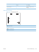

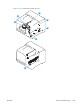
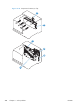
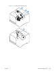
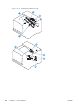
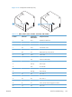


Figure 3-36 Component locations (6 of 6)
28
29
Table 3-13 PCAs, motors, fans, switches, solenoids, and clutches
Location Connector Component
abbreviation
Component name
1 J89 M12 Residual toner-feed motor
2 J26 FM2 Cartridge fan
3 J27 FM3 Delivery fan
4 J62 SW3 24V interlock switch
5 J118 SW1, SW2 5V interlock switch
6 J84 SL3 Multipurpose-tray pickup solenoid
7J780SW4Power switch
8 J86 CL1 Duplex re-pick clutch
9 ICB Interconnect board (ICB)
10 LVPS Low-voltage power supply
11 HVPS (t) HVPS-T upper
12 DCC DC Controller
13 J119 FM1 Power-supply fan
14 HVPS (d) HVPS-D (lower)
15 J41 M3 Drum motor 1
16 J40 M4 Drum motor 2
17 J42 M5 Drum motor 3
18 J25 M10 Development-disengagement motor
19 J8 SL1 Primary transfer roller disengagement solenoid
20 J15 M2 Fuser motor
ENWW
Tools for troubleshooting
291