
user manual
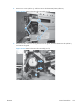


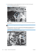

10. When the assembly is correctly installed against the chassis, the pin above the swing gear
protrudes through the hole in the chassis.
Figure 2-215 Reinstall the main drive assembly (10 of 11)
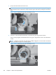
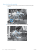
11. Install the main drive assembly mounting screws, and then reinstall the developing disengagement
motor (callout 1).
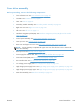
TIP: After reassembling the product, use the Diagnostics menu to print a Color Band Test
page.
If the test page shows one or more color planes are not printing (usually in the upper left corner of
the page), the cam or cams for the missing color plane are not correctly aligned. Repeat the
reinstall the main drive assembly procedure.
Figure 2-216 Reinstall the main drive assembly (11 of 11)
1
222 Chapter 2 Removal and replacement ENWW