
user manual
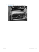

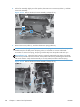

6. Disconnect six connectors (callout 1).
NOTE: Disconnect the larger connector on the right side from the bottom. Disconnect the two
smaller connectors on the right side from the top.
Figure 2-171 Remove the laser/scanner assembly (Y/M) (6 of 12)
1
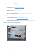
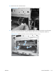
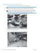
7. Release two tabs (callout 1), and then slide the fan assembly toward the power-supply side of the
product to release it.
Figure 2-172 Remove the laser/scanner assembly (Y/M) (7 of 12)
1
ENWW
Internal assemblies
189