
user manual
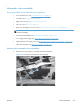
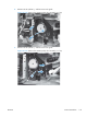


4. Release one tab (callout 1), and then remove the fan and fan duct (callout 2).
Figure 2-153 Remove the cassette pickup drive assembly (4 of 10)
1
2
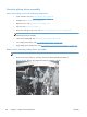
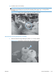
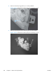
5. Disconnect five connectors (callout 1; J110, J111 on the DC controller PCA), release the FFCs
from the guide (callout 2), and then release the wire harnesses from the guides.
NOTE: To locate DC controller connector locations, see DC controller PCA on page 284.
Figure 2-154 Remove the cassette pickup drive assembly (5 of 10)
2
1
178 Chapter 2 Removal and replacement ENWW