
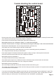
Manual

J1J1
LED5LED5
LED6LED6
LED4LED4
LED3LED3
LED2LED2
LED1LED1
J2J2
IC2IC2
021-650SE ISSUE 1021-650SE ISSUE 1
LABELLABEL
CONTROLCONTROL
PRODUCTIONPRODUCTION
HEDHED
CC
BB
AA
DC POWERDC POWER DC POWERDC POWER
RELAY 1RELAY 1RELAY 2RELAY 2RELAY 3RELAY 3RELAY 4RELAY 4
RELAY 6RELAY 6RELAY 5RELAY 5
REMOTE INDICATIONSREMOTE INDICATIONS
12 +VE12 +VE F INPUTSF INPUTS R INPUTSR INPUTS D INPUTSD INPUTS
CCDDSSXX
--------++++++++
GN4GN4
GN3GN3
GN2GN2
GN1GN1
RD4RD4
RD3RD3
RD2RD2
RD1RD1
++
++
++
++
F4F4
F3F3
F2F2
F1F1
D4D4
R4R4
D3D3
R3R3
D2D2
R2R2
R1R1
D1D1 NCNC
COMCOM
NONO
NCNC
COMCOM
NONO
NCNC
COMCOM
NONO
NCNC
COMCOM
NONO
NCNC
COMCOM
NONO
NCNC
COMCOM
NONO
NCNC
COMCOM
NONO
NONO
COMCOM
NCNC
NCNC NONOCOMCOMNCNC NONOCOMCOMNCNC NONOCOMCOMNONOCOMCOMNCNC
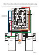
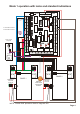
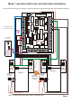
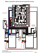
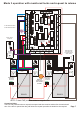
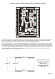
This setup allows for a common style of interlock, where 3 or 4 doors require interlocking as separate interlocks
with a common door. This would normally involve cross wiring between interlocks, but simply changing both
jumpers to position B allows an easy to connect 3 and 2 door combination interlock.
In the example, doors 1, 2 and 3 are interlocked, also door 3 is interlocked with door 4. However, doors 1 and 2
are not interlocked with door 4. All functions and indications are the same as the standard IG432. If the interlock
is breached, all 4 doors are considered as part of the problem. If there are only 3 doors in total, it is probably best
just to ignore door 1 and link D1 permanently to +ve to give the impression that the door is always closed. The
standard features; fire alarm, privacy and de-fog are all allowed in this mode. From a reliability point of view,
mode 1 operation is not permitted in this setup.
3 door 2 door interlocks with a common door
Page 12
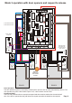
Door 4
Door 3
Door 2
Door 1
Three door two door
interlock example
with door 3
common to both
interlocks