
Manual

J1J1
LED5LED5
LED6LED6
LED4LED4
LED3LED3
LED2LED2
LED1LED1
J2J2
IC2IC2
021-650SE ISSUE 1021-650SE ISSUE 1
LABELLABEL
CONTROLCONTROL
PRODUCTIONPRODUCTION
HEDHED
CC
BB
AA
DC POWERDC POWER DC POWERDC POWER
RELAY 1RELAY 1RELAY 2RELAY 2RELAY 3RELAY 3RELAY 4RELAY 4
RELAY 6RELAY 6RELAY 5RELAY 5
REMOTE INDICATIONSREMOTE INDICATIONS
12 +VE12 +VE F INPUTSF INPUTS R INPUTSR INPUTS D INPUTSD INPUTS
CCDDSSXX
--------++++++++
GN4GN4
GN3GN3
GN2GN2
GN1GN1
RD4RD4
RD3RD3
RD2RD2
RD1RD1
++
++
++
++
F4F4
F3F3
F2F2
F1F1
D4D4
R4R4
D3D3
R3R3
D2D2
R2R2
R1R1
D1D1 NCNC
COMCOM
NONO
NCNC
COMCOM
NONO
NCNC
COMCOM
NONO
NCNC
COMCOM
NONO
NCNC
COMCOM
NONO
NCNC
COMCOM
NONO
NCNC
COMCOM
NONO
NONO
COMCOM
NCNC
NCNC NONOCOMCOMNCNC NONOCOMCOMNCNC NONOCOMCOMNONOCOMCOMNCNC
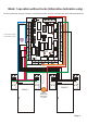
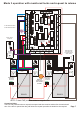
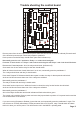
Remove power from the unit. Open all doors (Doors that have been linked out must be unlinked). Ensure that all
of the function inputs are open. Move both jumpers to position B.
Put the power on and all 6 relays should switch (have their indicators on).
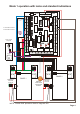
All of the relays should clear. (Indicators off).
Close each door in turn and the relay for that door should switch.
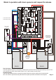
When all 4 doors have been closed, linked out if not in use, momentarily press the pushbutton C.
The 4 relays should clear and relay 5 should switch.
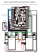
Press each Request To Release and while the request is made, the relay for that request should switch.
At the end of this test ensure that none of the 4 relays are switched.
Momentarily press the pushbutton C.
The relay 5 should clear and relay 6 should switch.
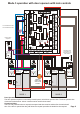
Close each function input in turn. While the function is closed, the relay for that function should switch.
At the end of this test ensure that none of the 4 relays are switched.
Momentarily press the pushbutton C.
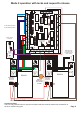
All 6 of the relays should clear and the led indicators all flash red and then green.
The control unit is working. Remove power and move the jumpers back to position A. Put power back on and the
unit should behave as an interlock.
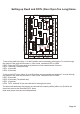
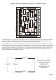
If you are not using Requests to Release, ignore that test, and momentarily press the pushbutton C again. The
unit will move on to Relay 6 illuminated. Fit the permanent link to F3 Function, relay 3 should switch and leave
this link in when you remove power. This will leave the unit in the MODE 1 operating state.
Momentarily press the unit C pushbutton. Relays 1 to 4 leds should extinguish.
Probe the 'X' terminal with +ve. Relays 5 and 6 leds should extinguish and Relays 3 and 4 leds should illuminate.
Remove the 'X' terminal probe.
Trouble shooting the control board
Page 11