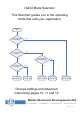
IG432 Mode Selection This flowchart guides you to the operating mode that suits your application.
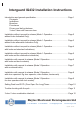
Interguard IG432 Installation Instructions Introduction and general specification............................................................. Page 1 Principals Indications Breaches Fire alarms Privacy and de-fog features 3 door 2 door with common door Installation without request to release (Mode 1 Operation.............................. Page 2 without locks Indication Only) Installation without request to release (Mode 1 Operation..............................
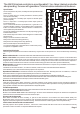
The IG432 Interlock controller is a configurable 2, 3 or 4 door interlock controller also providing the user with good door / interlock status indication at the doors.
Mode 1 operation without locks (Indication only).
Mode 1 operation without locks (Alternative Indication only). The door status leds are green instead of not being illuminated.
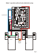
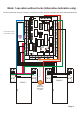
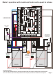
Mode 1 operation with locks and standard indications + + + + - NC COM NO R3 NC LED2 J1 COM J2 A B C F2 F3 NO NC COM Privacy button if required NO + + + + NC LED3 COM NO NC RD1 REMOTE INDICATIONS RELAY 3 12 +VE F4 COM RD2 NO LED4 021-650SE ISSUE 1 RD3 LED5 RD4 NC LED6 COM GN1 RELAY 4 R INPUTS R2 F1 F INPUTS NO LED1 RELAY 2 D3 RELAY 1 NC R4 mode 1 function link DC POWER COM R1 F2 Fire Alarm Function - D2 D4 F1 Fire Alarm Function - IC2 link unused door contac
Mode 1 operation with locks and alternative indications. The door status leds are green instead of not being illuminated.
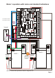
Mode 2 operation with locks and request to release + + + + - R2 NC COM NO R3 NC LED2 J1 COM J2 A B C F1 F2 F3 NO NC COM NO + + + + NC LED3 NO NC RD1 REMOTE INDICATIONS RELAY 3 COM COM RD2 NO LED4 021-650SE ISSUE 1 RD3 LED5 RD4 NC LED6 COM GN1 RELAY 4 12 +VE F4 Privacy button if required RELAY 1 NO LED1 RELAY 2 D3 IC2 R INPUTS DC POWER NC R4 F INPUTS - COM R1 F2 Fire Alarm Function - D2 D4 F1 Fire Alarm Function - D1 PRODUCTION CONTROL LABEL link unused do
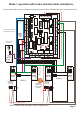
Mode 3 operation with monitored locks and request to release + + + + - R2 IC2 LED2 F3 J2 NO NC COM NO + + + + NC LED3 COM NO NC RD1 REMOTE INDICATIONS RELAY 3 12 +VE F4 Privacy button if required NC COM A B C F2 RELAY 1 NO R3 J1 NC COM COM RD2 NO LED4 021-650SE ISSUE 1 RD3 LED5 RD4 NC LED6 COM GN1 RELAY 4 R INPUTS NO LED1 RELAY 2 D3 F1 F INPUTS DC POWER NC R4 mode 3 function link - COM R1 F2 Fire Alarm Function - D2 D4 F1 Fire Alarm Function - D1 PRODUCT
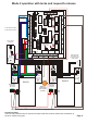
Mode 3 operation with door openers and request to release + + + + - R2 IC2 LED2 F3 J2 NO NC COM NO + + + + NC LED3 COM NO NC RD1 REMOTE INDICATIONS RELAY 3 12 +VE F4 Privacy button if required NC COM A B C F2 RELAY 1 NO R3 J1 NC COM COM RD2 NO LED4 021-650SE ISSUE 1 RD3 LED5 RD4 NC LED6 COM GN1 RELAY 4 R INPUTS NO LED1 RELAY 2 D3 F1 F INPUTS DC POWER NC R4 mode 3 function link - COM R1 F2 Fire Alarm Function - D2 D4 F1 Fire Alarm Function - D1 PRODUCTION
Mode 3 operation with door openers with lock controls + + + + - R2 COM NO R3 NC LED2 J1 COM J2 A B C F2 F3 NO NC COM NO + + + + NC LED3 NO NC RD1 REMOTE INDICATIONS RELAY 3 COM COM RD2 NO LED4 021-650SE ISSUE 1 RD3 LED5 RD4 NC LED6 COM GN1 RELAY 4 12 +VE F4 Privacy button if required RELAY 1 NC IC2 R INPUTS NO LED1 RELAY 2 D3 F1 F INPUTS DC POWER NC R4 mode 3 function link - COM R1 F2 Fire Alarm Function - D2 D4 F1 Fire Alarm Function - D1 PRODUCTION CO
Setting up Dwell and DOTL (Door Open Too Long) times.
Trouble shooting the control board DC POWER NC COM NO R2 IC2 LED1 NO R3 LED2 R4 J1 F2 F3 NO NC COM NO + + + + NC LED3 NO NC RD1 RELAY 3 COM COM RD2 NO LED4 021-650SE ISSUE 1 RD3 LED5 RD4 NC LED6 COM GN1 NO GN2 NC GN3 COM RELAY 4 12 +VE F4 REMOTE INDICATIONS NC COM J2 A B C F1 NC COM RELAY 2 D3 PRODUCTION CONTROL LABEL D INPUTS - D2 R1 R INPUTS - D1 D4 F INPUTS - RELAY 1 + + + + - DC POWER HED GN4 NO X S D C NC COM NO NC COM NO NC COM NO RELA
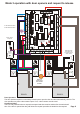
3 door 2 door interlocks with a common door DC POWER NC COM NO R2 IC2 LED1 NO R3 LED2 R4 J1 F2 F3 J2 NO NC COM NO + + + + NC LED3 NO NC RD1 RELAY 3 COM COM RD2 NO LED4 021-650SE ISSUE 1 RD3 LED5 RD4 NC LED6 COM GN1 NO GN2 NC GN3 COM RELAY 4 12 +VE F4 REMOTE INDICATIONS NC COM A B C F1 NC COM RELAY 2 D3 PRODUCTION CONTROL LABEL D INPUTS - D2 R1 R INPUTS - D1 D4 F INPUTS - RELAY 1 + + + + - DC POWER HED GN4 NO X S D C NC COM NO NC COM NO RELAY