
Instruction Manual
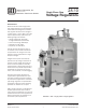

SVR-1 Single-Phase Step Voltage Regulators
28-10
Copyright © 2011 Howard Industries, Inc.
2
Document No. 2.4.132
Revision: 0
Issued: October, 2011
Howard Industries, Inc.
Laurel, MS 39440
www.howardtransformers.com
The SVR-1 features sealed-tank
construction and a 65°C rise insulation
system, which allows 55°C rise rated
designs to provide an additional 12%
capacity above nameplate rating
without loss of normal insulation
life. The HI-AMP™ feature provides
capability for additional load capacity,
as long as the regulator’s maximum
current rating is not exceeded.
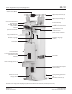
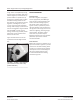
The regulator’s complete internal
assembly (including tap-changer
switch, motor, core-and-coil assembly,
and reactor coil-and-coil assembly) is
mounted to the cover (Figure 2). This
construction simplies removal of
the internal assembly for inspection,
maintenance, and repair.
_______________________________
SVR-1 voltage regulators are designed,
manufactured, and tested in
accordance with the requirements of
ANSI Standard C57.15.
STANDARD REGULATOR FEATURES
All SVR-1 voltage regulators are
supplied with the following standard
accessories and features:
• Gear-driven tap-changer switch with
motor and power supply
• Motor capacitor mounted in control
enclosure for ease of replacement
• Mechanical tap position indicator
with externally adjustable HI-AMP™
limit switches
• Laser-etched nameplates (two)
• Lifting lugs
• Oil drain valve with sampling device
• Upper lter press connection
• Oil sight gauge
• High-creep porcelain bushings
• Bolt-down provisions (overhead type
regulators)
• Pole mounting brackets (overhead
type regulators)
• Rectangular substation base
(substation type regulators)
• Externally mounted series arrester
(MOV type)
• Mounting provisions for shunt
arresters
• Automatic pressure relief device
• Powder coated mild steel tank, cover,
clamp ring, and control enclosure
• HI/ICMI UVR-1 digital regulator
control (refer to description below)
OPTIONS
The following optional features and
accessories are available for the SVR-1
voltage regulator:
• Externally mounted shunt arresters
(MOV type)
• Wildlife protection for high-voltage
bushing terminals and lightning
arresters
• Extra-length control cable
• PTs and CTs for external metering
• Elevating platform
• Control enclosure heater
• 4-hole NEMA H-spade connectors
• Cooling fans
• Powder coated stainless steel
tank, cover, clamp ring, and control
enclosure
• HI/ICMI USC-1 simplied regulator
control
• Beckwith digital regulator control
• SEL digital regulator control
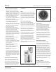
HI/ICMI UVR-1 CONTROL
The HI/ICMI UVR-1 digital regulator
control (Figure 3) has the following
standard features and options:
• Digital processing and nonvolatile
ash technology data storage with
Motorola 32-bit processor
• Mil-spec modular design with Mil-std
I-46085 conformal coated circuit
boards
• Solid-state tap-changer relays
• Corrosion resistant panel/shield
• Bright white/blue LCD high-visibility
display
• Super-bright LED indicators, including
High Band, In Band, Low Band, High
Limit, Low Limit, Voltage Reduction,
Reverse Power, Neutral Position, and
Alert
• DNP 3.0 Level 2, report-by-exception
communications protocol with ACS
worldwide certication
• Multiple, interoperable
communications ports, including
RS-232, IEEE-485 two and four-wire,
front panel serial program port, ber
optic interface, ethernet capable,
TCP/IP (optional), Bluetooth wireless
(optional), and eight-port input/output
board (optional)
• Certications: radio frequency
interference withstand capability per
ANSI/IEEE C37.90.2, electrostatic
(continued on Page 4)
FIGURE 2: Internal Assembly
FIGURE 3: HI/ICMI UVR-1 Control