
Manual

Switch-Pad™ SVR-1 Step Voltage Regulator
Document No. 2.4.114
Revision: 03
Issued: March, 2012
17
Copyright © 2012 Howard Industries, Inc.
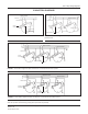
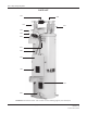
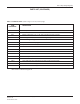
PARTS lIST (CONTINUED)
ITEM DESCRIPTION
REFERENCE
003 Nameplate
004 Pressure Relief Valve
015 Bushing Assembly (“S” or “SL” with standard mounting clamp)
020 Bushing Assembly (“L” with CT mounting clamp)
057 Oil Level Sight Gauge
060 Drain Valve with Sampling Device
151 By-Pass Arrester Assembly
158 Position Indicator
160 Flexible Conduit Assembly
161 Control Enclosure
163 Terminal Block Enclosure
162* Motor Capacitor (located inside control enclosure)
165* Control Panel (located inside control enclosure)
155* Cover Mounted Terminal Block (located inside terminal block)
156* Controller Terminal Strip (male connector, located inside control enclosure)
157* Controller Terminal Strip (female connector, located inside control enclosure)
*Not shown in reference Figure 12
TAblE 1: ExTERNAl PARTS - (Refer to Figure 1 on the previous page)