
User guide

Copyright © 2010 Howard Industries, Inc.
2
Howard Industries, Inc.
Laurel, MS 39440
www.howardtransformers.com
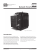
Network Transformer94-10
Catalog Section 94-10
Network Transformers
Issued: April 9, 2010
Transformer Design
Howard network transformers are designed with conser-
vative mechanical and electrical margins to withstand
the harsh environments encountered in today’s network
distribution systems. Core-and-coil designs are optimized
for the lowest procurement cost or lowest total owning
cost according to each customer’s specic requirements.
All designs are guaranteed to meet the U.S. Department of
Energy’s minimum efciency standards. General industry
standards applicable to Howard network transformer de-
signs include IEEE C57.12.00 Standard General Require-
ments for Liquid-Immersed Distribution, Power, and Regu-
lating Transformers, ANSI C57.12.40 American National
Standard for Secondary Network Transformers, Subway
and Vault Types (Liquid Immersed)—Requirements, IEEE
C57.12.90 Standard Test Code for Liquid-Immersed Distri-
bution, Power and Regulating Transformers and Guide for
Short Circuit Testing of Distribution and Power Transform-
ers, IEEE C57.93 Guide for Installation of Liquid-Immersed
Power Transformers, IEEE C57.98 Guide for Transformer
Impulse Tests, IEEE C57.100 Standard Test Procedure for
Thermal Evaluation of Oil Immersed Distribution Trans-
formers, 10 CFR Part 431, Department of Energy, Energy
Conservation Program for Commercial Equipment: Distri-
bution Transformers Energy Conservation Standards; Final
Rule, and 10 CFR Part 431, Department of Energy, Energy
Conservation Program: Test Procedures for Distribution
Transformers; Final Rule.
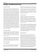
Core-and-Coil Design
Howard’s ve-legged core-form design provides excellent
mechanical strength that has been proven through rigor-
ous design verication testing and years of eld service.
Mechanical strength is achieved through the use of a rug-
ged steel mounting frame that provides solid support for
core/coil assembly.
Core-and-coil designs are optimized to provide the lowest
total owning cost or lowest purchase price according to
each customer’s specications. In addition, all network
transformer ratings, where applicable, are designed to
satisfy the minimum efciency standards set by the U.S.
Department of Energy.
Core Construction
Cores are fabricated using high-efciency grain-oriented
silicon steel that has been precision slit and edge con-
ditioned by the supplier. Step-lap joints are used to
minimize losses and exciting current, and to insure quiet
operation. Cores are designed to operate at ux densities
well below saturation. Stress-relief annealing is employed
to maximize efciency and establish the required rectan-
gular shape of each core loop. Prior to assembly each
core is carefully tested to ensure it meets dimensional, ex-
citing current and no-load loss specications. Amorphous
metal cores are available for those applications requiring
ultra-low excitation losses.
Coil Construction
High-voltage coil windings are constructed of copper
or aluminum magnet wire. Automatic wire tensioners,
computer-controlled traverse mechanisms and laser
alignment systems ensure that coils are wound tightly and
accurately. Low-voltage coil windings are constructed of
edge-conditioned full-width sheet conductor, available in
either copper or aluminum. Low-voltage sheet windings
provide the advantage of virtually eliminating axial forces
during short circuit.
Turn-to-turn insulation in the high-voltage winding is Form-
var® or extruded polymer coating. Main barrier and layer
insulation in both low-voltage and high-voltage windings is
thermally-upgraded craft, providing exceptional insulation
life. Insulation paper is coated with a thermoset epoxy
adhesive throughout the coil to produce excellent layer-
to-layer bonding. Strategically placed oil ducts provide
oil ow and adequate cooling throughout the windings.
The insulation system is designed to provide exceptional
impulse withstand capability.
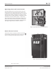
Tank Construction
Network transformer tanks are of sealed construction,
including a sub-base and a welded main cover with
bolted (standard) or welded hand-hole cover. The sub-
base consists of steel bars parallel to the long axis of the
transformer with jacking areas located along the length
and width of the tank bottom. The copper-bearing steel
plate used to construct the tank is reinforced with side
wall braces, and all tank seams are continuously welded.
The completely sealed tank is capable of withstanding a
pressure of 7 psig without permanent deformation and
15 psig without rupture. Four lifting lugs are supplied and
arranged for lifting of the complete transformer includ-
ing the network protector, if attached. Tank grounding
provisions consist of copper-faced or stainless-steel pads
welded to the tank. Fastening hardware is composed of
corrosion-resistant steel. The tank exterior nish is in ac-
cordance to the requirements of ANSI C57.12.40.
Design and Manufacturing