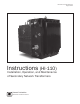
Network Transformer Instruction Manual Document 2.4.
Document 2.4.128, Revision 2 August, 2012 Network Transformer Instruction Manual READ THIS IMPORTANT SAFETY INFORMATION Read these instructions carefully and become familiar with the equipment before proceeding with installation, operation, or maintenance activities. This equipment contains extremely hazardous voltages. To prevent death, serious personal injury, or equipment damage, all information in these instructions should be read and observed.
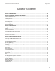
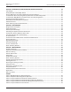
Network Transformer Instruction Manual Document 2.4.128, Revision 2 August, 2012 Table of Contents SECTION 1: INTRODUCTION..............................................................................................................................5 SECTION 2: RECEIVING, HANDLING AND STORAGE.......................................................................................6 Drawings and Documents ..........................................................................................................
Document 2.4.128, Revision 2 August, 2012 Network Transformer Instruction Manual SECTION 5: OPERATION OF SWITCHING AND PROTECTIVE DEVICES........................................................... 14 Tap Changer ...................................................................................................................................................... 15 Series/Multiple or Delta/Wye Switch ............................................................................................................
Document 2.4.128, Revision 2 August, 2012 Network Transformer Instruction Manual SECTION 1: INTRODUCTION This document is intended as a general guide for the installation, operation and maintenance of Howard Industries secondary network transformers. Although efforts have been made to ensure accuracy and completeness, these instructions do not address every conceivable application or circumstance that might be encountered. Features presented herein may not be present in all transformer designs.
Document 2.4.128, Revision 2 August, 2012 Network Transformer Instruction Manual SECTION 2: RECEIVING, HANDLING AND STORAGE Drawings and Documents Locate all shipping papers, packing lists, outline drawings, and other pertinent information for use during inspection. The transformer outline drawing indicates the location of nameplates and provides physical dimensions and weights. The nameplate provides electrical characteristics, winding connections, and weights.
Network Transformer Instruction Manual 3. C heck the main tank, primary switch chamber and primary terminal chamber for indication of fluid leaks, looking carefully at weld seams, bushings, gauges, valves and all other main tank and chamber fittings. If suspicious indications are found, investigate thoroughly to determine if a leak does exist on the transformer. Indications of a leak can sometimes be residual fluid that was not cleaned during the manufacturing process and not an actual leak.
Document 2.4.128, Revision 2 August, 2012 containers. Do not store the transformer in a corrosive environment. If the transformer is to be stored for an extended period of time before being placed into service, it should be stored on a firm level surface. The gas space above the insulating fluid should be pressurized with dry nitrogen to a pressure of 2-3 PSIG. This will prevent a negative internal pressure that might draw moisture into the main tank, switch chamber, or terminal chamber.
Document 2.4.128, Revision 2 August, 2012 Network Transformer Instruction Manual SECTION 3: INSTALLATION Lifting and Handling Lifting hooks are provided near the top of the transformer tank for lifting. All four lifting hooks must be used simultaneously. The transformer must not be lifted from any points other than the provided lifting hooks. Do not use holes in the lifting hooks for lifting. These holes are for tie-down purposes only and are not suitable for lifting.
Document 2.4.128, Revision 2 August, 2012 depend on the transformer kVA, efficiency and load cycle. Forced ventilation may be required to adequately cool the transformer. Refer to the National Electric Code for recommended vault ventilation. Before placing the transformer in service, remove any shipping braces and packing material that may have been attached at the factory. Grounding The transformer must be permanently grounded according to applicable local and national codes.
Document 2.4.128, Revision 2 August, 2012 Network Transformer Instruction Manual BEFORE AND AFTER INITIAL ERGIZATION SECTION 4: INSPECTION AND TESTING DANGER FAILURE TO FOLLOW THE INSTRUCTIONS BELOW will result IN death or serious personal injury and may also result in damage to the equipment.
Document 2.4.128, Revision 2 August, 2012 board located under oil in the transformer tank. Refer to “Opening the Transformer Tank” for instructions. 4. Tap Changer Setting For transformers supplied with high-voltage taps, check the tap changer setting to ensure it is set to the proper position for the required voltage. The tap changer setting must not be changed while the transformer is energized.
Network Transformer Instruction Manual Post-Energization Inspection and Tests After the transformer is energized, the following tests and inspections should be performed. DANGER FAILURE TO FOLLOW THE INSTRUCTIONS BELOW will result IN death or serious personal injury and may also result in damage to the equipment.
Document 2.4.128, Revision 2 August, 2012 Network Transformer Instruction Manual SECTION 5: OPERATION OF SWITCHING AND PROTECTIVE DEVICES The following operating instructions and descriptions of switching and protective devices are intended to be a general guide for operation of Howard secondary network transformers in normal environments.
Network Transformer Instruction Manual Tap Changer The de-energized (no-load) tap changer may be used to adjust the voltage ratio of a transformer while it is de-energized. It is intended to allow adjustment of the output (secondary) voltage to the rated value. Do not use the tap changer to raise or lower the output voltage to any voltage other than that indicated on the transformer nameplate.
Document 2.4.128, Revision 2 August, 2012 Primary Disconnect and Grounding Switch Network transformers are normally supplied with a three-position primary disconnect switch (sometimes called a “network switch”), which is housed in a fluidfilled chamber welded to the main tank below the primary terminal chamber.
Document 2.4.128, Revision 2 August, 2012 Network Transformer Instruction Manual Operation of the three-position mag-break switch is similar to that of the three-position non-interrupting switch. Before attempting to operate the mag-break switch, verify that the network protector is in the open position. WARNING FAILURE TO FOLLOW THE INSTRUCTIONS BELOW COULD RESULT IN DEATH OR SERIOUS PERSONAL INJURY AND MAY ALSO RESULT IN DAMAGE TO THE EQUIPMENT.
Document 2.4.128, Revision 2 August, 2012 Network Transformer Instruction Manual SECTION 6: ACCESSORIES Some of the accessory devices described below are optional and may not be present in any particular transformer design. The inclusion of particular accessory device in any transformer design is governed by industry standards and by individual user specifications.
Network Transformer Instruction Manual Document 2.4.128, Revision 2 August, 2012 Air Test Provision The air test provision is located on the primary switch chamber above the 85°C fluid level. The provision consists of a 0.5-inch NPT opening with protective plug, which can be used for testing the air inside the switch chamber. Primary Entrance The primary entrance is located on the top of the terminal chamber and is provided for connection to the primary feeders.
Document 2.4.128, Revision 2 August, 2012 Secondary Bushings Three externally-removable secondary bushings are bolted to the main tank wall inside the secondary throat. Each is fitted with a flexible connector for connection to a network protector. The low-voltage neutral connection consists of a blade welded to the main tank or, when specified by the user, a fullyinsulated bushing.
Document 2.4.128, Revision 2 August, 2012 Network Transformer Instruction Manual SECTION 7: MAINTENANCE WARNING FAILURE TO FOLLOW THE INSTRUCTIONS BELOW COULD RESULT IN DEATH OR SERIOUS PERSONAL INJURY, AND MAY ALSO RESULT IN DAMAGE TO THE EQUIPMENT. The transformer must be de-energized before performing any maintenance work. Transformers should be inspected periodically while in service, with the frequency of inspection determined by service conditions.
Document 2.4.128, Revision 2 August, 2012 8. C heck all fasteners for signs of corrosion and replace as necessary. 9. C heck fluid temperature gauges, including the maximum temperature drag hand (if present) to determine whether the fluid temperature has exceeded the design limit. Any such indication should be investigated to determine and correct the cause. 10. Check torque values on all ground connections and tighten as necessary. Refer to torque guidelines contained in Table 6. 11.
Network Transformer Instruction Manual 1. I nsulation Resistance Test. Refer to “Insulation Resistance Test” for instructions. 2. T urns Ratio Test. Refer to “Ratio Test” for instructions. 3. I nsulation Power Factor Test (This test cannot be performed on a transformer having a secondary neutral that is solidly grounded.) 4. F luid quality tests, such as moisture content, power factor, dielectric strength and dissolved gas analysis.
Document 2.4.128, Revision 2 August, 2012 Other Accessory Devices Other accessories devices, such as a gauges and valves typically require no maintenance except for replacement in the event of malfunction or damage. Sampling and Testing the Fluid Before sampling the insulating fluid, de-energize the transformer and make sure all bushings and terminals are effectively grounded. Samples should be drawn from the bottom of the tank.
Network Transformer Instruction Manual water and other possible contaminants before proceeding with the filling process 2. P ump from the bottom of the storage container. To prevent bubbles in the fluid, do not allow air to enter the pump intake. 3. P lace the discharge hose at the bottom of the transformer tank below the fluid surface to prevent aeration and the introduction of bubbles. 4. P ump and fill the transformer tank slowly.
Document 2.4.128, Revision 2 August, 2012 Network Transformer Instruction Manual tank-mounted components are over tightened. Check with the Howard Industries Transformer Division for recommended torque values for any devices or connections not listed below. Use manufacturer’s recommended torque values for any user-supplied devices.
Document 2.4.
Document 2.4.128, Revision 2 August, 2012 Network Transformer Instruction Manual HI-110 Instructions for Installation, Operation and Maintenance of Secondary Network Transformers Document 2.4.128, Revision 2, August, 2012 Copyright © 2012, Howard Industries, Inc. Laurel, Mississippi Telephone: 601-425-3151 Fax: 601-649-8090 Email: mkt@howard.com Web: howardtransformers.