Single-Phase Pad-Mounted Compartmental-Type Distribution Transformers Document 2.4.
Document 2.4.96, Revision 0 March, 2013 Single-Phase Pad-Mounted Compartmental-Type Distribution Transformers ! READ THIS IMPORTANT SAFETY INFORMATION ▲ READ THIS ENTIRE INSTRUCTION MANUAL CAREFULLY AND BECOME FAMILIAR WITH THE EQUIPMENT AND ALL SAFETY-RELATED INFORMATION BEFORE PROCEEDING WITH INSTALLATION, OPERATION, OR MAINTENANCE ACTIVITIES. Safe use of this equipment is dependent on proper installation, operation, and maintenance procedures. Follow all applicable local and national codes.
Single-Phase Pad-Mounted Compartmental-Type Distribution Transformers Document 2.4.
Document 2.4.
Single-Phase Pad-Mounted Compartmental-Type Distribution Transformers Document 2.4.96, Revision 0 March, 2013 SECTION 1: INTRODUCTION This document is intended as a general guide for the installation, operation and maintenance of Howard Industries fluid-filled, single-phase, pad-mounted compartmental-type distribution transformers.
Document 2.4.96, Revision 0 March, 2013 Single-Phase Pad-Mounted Compartmental-Type Distribution Transformers SECTION 2: RECEIVING, HANDLING, AND STORAGE Drawings and Documents Locate all shipping papers, packing lists, specifications, and other pertinent information for use during inspection. Verify that the transformer is supplied with a nameplate, required warning labels, and terminal designation markings. Verify that the terminal designation markings are consistent with those on the nameplate.
Single-Phase Pad-Mounted Compartmental-Type Distribution Transformers Before unloading the transformer, the following checks should be performed: 1. Read the serial number on the transformer nameplate and make sure it matches the serial number listed on the shipping documents. Also, check the nameplate for kVA rating, high-voltage rating, lowvoltage rating, impedance and other design characteristics, and make sure they comply with the specifications. 2.
Document 2.4.96, Revision 0 March, 2013 Single-Phase Pad-Mounted Compartmental-Type Distribution Transformers ! WARNING ▲ FAILURE TO FOLLOW THE INSTRUCTIONS BELOW COULD RESULT IN DEATH OR SERIOUS PERSONAL INJURY, AND COULD ALSO RESULT IN DAMAGE TO THE EQUIPMENT. • D o not energize the transformer if the fluid level is low. • M aintain proper fluid level at all times while the transformer is energized.
Single-Phase Pad-Mounted Compartmental-Type Distribution Transformers Document 2.4.96, Revision 0 March, 2013 SECTION 3: INSTALLATION Lifting and Handling Lifting lugs or bosses are provided to lift the completely assembled transformer. All lifting lugs or bosses must be used simultaneously to provide a safe, balanced lift. The transformer must not be lifted from any points other than the provided lifting lugs or bosses. Do not use holes in the lifting hooks for lifting.
Document 2.4.96, Revision 0 March, 2013 Single-Phase Pad-Mounted Compartmental-Type Distribution Transformers assembled transformer. The transformer should sit flush with the mounting surface, so that there are no gaps that might compromise tamper resistance of the terminal compartment. The installed transformer should not tilt in any direction more than three degrees.
Single-Phase Pad-Mounted Compartmental-Type Distribution Transformers Document 2.4.96, Revision 0 March, 2013 with the universal bushing wells. Do not use incompatible or improperly rated bushing inserts, or equipment damage could occur. When installing inserts, follow the manufacturer’s instructions accompanying the inserts. Insulated dead-end caps or plugs must be installed on all unused high-voltage bushings before energizing.
Document 2.4.96, Revision 0 March, 2013 Single-Phase Pad-Mounted Compartmental-Type Distribution Transformers SECTION 4: INSPECTION AND TESTING BEFORE AND AFTER INITIAL ENERGIZATION Pre-Energization Inspection and Tests After the transformer has been installed, but before it is energized, the following tests and checks should be performed at a minimum to ensure that the transformer is ready to be energized. Do not energize the transformer without performing these tests and checks.
Single-Phase Pad-Mounted Compartmental-Type Distribution Transformers pressure relief valve, being careful to avoid any hot fluid that might be expelled from the valve. When reinstalling the plug, apply an appropriate thread sealing compound to prevent a fluid leak. Be aware that fluid temperature and orientation of the transformer tank will cause the fluid level to vary. Transformers are filled to a level that corresponds to a fluid temperature of 25°C.
Document 2.4.96, Revision 0 March, 2013 Single-Phase Pad-Mounted Compartmental-Type Distribution Transformers 2. C hecking for Leaks—Check the tank to make sure there are no fluid leaks. 3. O bserving Operation—After the transformer is initially energized, visually inspect it periodically, to make sure that no abnormal conditions are observed. 4. C hecking Gauges—Observe the fluid level and fluid temperature gauges, if provided, to confirm the proper fluid level and temperature. 5.
Single-Phase Pad-Mounted Compartmental-Type Distribution Transformers Document 2.4.96, Revision 0 March, 2013 SECTION 5: OPERATION OF SWITCHING AND PROTECTIVE DEVICES The following operating instructions and descriptions of switching and fusing devices are intended to be a general guide for operation of Howard single-phase pad-mounted transformers in normal environments.
Document 2.4.96, Revision 0 March, 2013 Single-Phase Pad-Mounted Compartmental-Type Distribution Transformers Hot-Stick Operable Devices Some devices such as draw-out expulsion fuses, dry-well canister fuses, dead-front high-voltage elbow terminations, rotary load-break switches and automatic pressure relief valves are designed to be operated with a live-line tool (hot stick or shotgun stick). Do not attempt to operate by hand any device that is designed to be operated with a live-line tool.
Single-Phase Pad-Mounted Compartmental-Type Distribution Transformers between its present setting and the next setting. The index plate prevents the switch from switching more than one position at a time. The live-line tool is then inserted into the switch operating handle and turned until the switch snaps into the next position. Repeat this procedure until the switch is in the desired position.
Document 2.4.96, Revision 0 March, 2013 Single-Phase Pad-Mounted Compartmental-Type Distribution Transformers On double-door style transformers the fuse can be inspected and replaced through the cover-mounted handhole using the following procedure. 1. M ake sure that the transformer is completely deenergized and that the tank and all primary and secondary terminals are securely and effectively grounded. 2.
Single-Phase Pad-Mounted Compartmental-Type Distribution Transformers 1. V ent the transformer by operating the PRV. Keep the valve open until the sound of air venting can no longer be heard. Be careful to avoid contact with any hot oil that might be expelled from the PRV. 2. S tand to one side of the Bay-O-Net device being operated. 3. Attach a live-line tool to the holder eye. 4. Twist the live-line tool to unlock the fuse holder. 5.
Document 2.4.96, Revision 0 March, 2013 Single-Phase Pad-Mounted Compartmental-Type Distribution Transformers Internal Partial-Range Current-Limiting Fuse The optional internal partial-range (backup) currentlimiting fuse is connected in series with a low-current interrupting device, such as a weak-link cartridge fuse or a Bay-O-Net expulsion fuse.
Document 2.4.96, Revision 0 March, 2013 Single-Phase Pad-Mounted Compartmental-Type Distribution Transformers An optional arrester disconnector provides a means to disconnect the fluid-immersed MOV arrester ground for transformer testing without entering the transformer tank. Two different styles of disconnectors are available, one manufactured by ERMCO Components Inc. (ECI) and one manufactured by Cooper Power Systems (CPS). These two styles operate differently as indicated below.
Document 2.4.96, Revision 0 March, 2013 Single-Phase Pad-Mounted Compartmental-Type Distribution Transformers Low-Voltage Circuit Breaker The optional low-voltage circuit breaker is mounted inside the tank and is fluid immersed. The breaker uses an automatic trip system to help protect the transformer from damage caused by overloads and short circuits. The presence of a low-voltage circuit breaker will be indicated on the transformer nameplate.
Single-Phase Pad-Mounted Compartmental-Type Distribution Transformers An optional trip indicator is available, consisting of an indicator lens which appears orange when the interrupter is in the TRIPPED position. Some Magnex Interrupters are supplied with an optional emergency overload setting. The emergency overload will allow approximately 30% overload before tripping. Using a live-line tool (hot stick), operate the emergency overload as follows. Document 2.4.
Document 2.4.96, Revision 0 March, 2013 Single-Phase Pad-Mounted Compartmental-Type Distribution Transformers SECTION 6: OPERATION OF TERMINAL COMPARTMENT, BUSHINGS, GAUGES AND ACCESSORY DEVICES Some of the devices described below are optional and may not be present in any particular transformer design. The inclusion of particular accessory devices in any transformer design is governed by industry standards and by individual user specifications.
Single-Phase Pad-Mounted Compartmental-Type Distribution Transformers Refer to “Sampling and Testing the Fluid” for the fluid sampling. Document 2.4.96, Revision 0 March, 2013 ! WARNING ▲ Automatic Pressure Relief Valve The automatic pressure relief valve (PRV) is designed to relieve excessive tank pressure that might occur during normal operation of the transformer. The valve consists of a self-resealing, spring-loaded diaphragm.
Document 2.4.96, Revision 0 March, 2013 Single-Phase Pad-Mounted Compartmental-Type Distribution Transformers front construction are usually provided with externally-clamped porcelain high-voltage bushings for connection to the high-voltage source. Bushings are usually provided with tin-plated eye-bolt terminals that are suitable for connection to either aluminum or copper conductors.
Single-Phase Pad-Mounted Compartmental-Type Distribution Transformers sure the cabinet is secure and tamper proof. Make sure the transformer and sill are sitting flush on the mounting pad with no gaps that might allow entry of a foreign object into the terminal compartment. Document 2.4.96, Revision 0 March, 2013 Other Accessory Devices Transformers may be provided with accessory devices not discussed in these instructions.
Document 2.4.96, Revision 0 March, 2013 Single-Phase Pad-Mounted Compartmental-Type Distribution Transformers SECTION 7: MAINTENANCE AND REPAIR These instructions are intended as a general guide for the maintenance of Howard single-phase padmounted distribution transformers, when used in typical applications and operated in normal environments.
Single-Phase Pad-Mounted Compartmental-Type Distribution Transformers 9. I nspect the base of the terminal compartment and make sure that it is sitting level and flat on the mounting pad with no gaps that might compromise tamper-resistance. 10 Check bushings, gauges, switches, fuse holders, valves and all other accessories for proper operation and repair or replace any defective devices. 11. Check all fasteners for signs of corrosion and replace as necessary. 12.
Document 2.4.96, Revision 0 March, 2013 Single-Phase Pad-Mounted Compartmental-Type Distribution Transformers 4. Fluid quality tests, such as moisture content, power factor, dielectric strength and dissolved gas analysis. Exterior Paint Finish Any damage to the exterior paint finish that exposes the primer coat or bare metal should be repaired immediately in order to prevent corrosion. Areas to be repaired should be thoroughly clean and dry.
Single-Phase Pad-Mounted Compartmental-Type Distribution Transformers dard C57.12.90 Test Code for Liquid-Immersed Distribution, Power, and Regulating Transformers for more information about design sound levels and factory sound testing. Low-Voltage Circuit Breaker The low-voltage circuit breaker is inaccessible (except in the double-door style transformer) and typically requires no maintenance.
Document 2.4.96, Revision 0 March, 2013 Single-Phase Pad-Mounted Compartmental-Type Distribution Transformers prevent aeration and the introduction of bubbles. In the case of a double-door style transformer, the discharge hose can be inserted through the cover-mounted handhole and placed at the bottom of the tank. 4. F ill the transformer tank slowly. Fill with fluid to fill line marked inside the transformer tank on the interior surface of the front panel.
Single-Phase Pad-Mounted Compartmental-Type Distribution Transformers 2. R e-install the handhole cover. Re-install fasteners according to the torque recommendations in Table 1. After tightening all fasteners, re-torque each one to ensure proper torque. 3. P ressurize the headspace to 3-4 PSIG and check for fluid leaks. This pressure should be maintained for at least four hours, followed by another leak check.
Document 2.4.
Single-Phase Pad-Mounted Compartmental-Type Distribution Transformers Document 2.4.
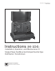
Document 2.4.96, Revision 0 March, 2013 Single-Phase Pad-Mounted Compartmental-Type Distribution Transformers HI-104 Instructions for the Installation, Operation, and Maintenance of Single-Phase Pad-mounted Distribution Transformers Document 2.4.96, Revision 0 (March, 2013) Copyright © 2012, Howard Industries, Inc. Laurel, Mississippi Telephone: 601-425-3151 Fax: 601-649-8090 Email: mkt@howard.com Web: www.howardtransformers.