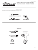
Reverso en español HWGWTB2-1 OPTIONAL BLOWER Installation Instructions Instructions must be left with the owner for future reference after installation. Hardware Package Replacement screws and anchors can be purchased at major hardware stores.
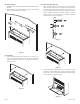
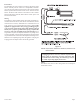
Installing the Blower 1. Install furnace according to Installation Instructions and Owner's Manual. 2. Refer to Figure 1 for measurements to locate two (2) mounting holes on wall surface above furnace On Sheet Rock Wall (Drywall) 3. After locating mounting holes, drill two (2) 5/16" diameter holes into wall. Insert the two (2) plastic expansion anchors provided in blower kit into holes. Insert two (2) #10 x 1 1/2" screws provided in blower kit into plastic expansion anchors.
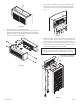
7. Position blower housing on top of header assembly. Align key hole slots on back of blower housing with the two (2) screws attached to wall. Do not tighten housing mounting screws Figure 6 5. 6. Remove the outer casing and place aside. Remove (4) 8 x 3/8" screws that attach blower front to blower housing. Separate blower front from blower housing. Remove blower front by disconnecting fan control switch wire assembly from power cord and motor wire. Figure 8. 8.
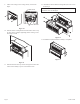
9. Attach outer casing to inner casing with (2) screws from Step 4. SCREW HOLES 12. Attach blower front to blower housing with (4) 8 x 3/8" screws from Step 6. Caution: When installing blower housing onto wall be careful motor coil is not damaged. CASING BRACKET Figure 10 10. Position blower housing flush with wall surface and on top of outer casing. Complete tightening blower housing screws from Step 3 to wall. Figure 12 13. Installation of optional blower assembly is completed.
Fan Control The automatic fan control switch is located on the bottom of the blower assembly. The fan control is a nonadjustable, automatic type. The fan control will require between 3 and 7 minutes of main burner operation before the fan control "closes" and activates the blower. The blower will continue to run between 3 and 7 minutes after the main burner shuts off, before the fan control "opens" and deactivates the blower.
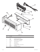
PARTS LIST Page 6 INDEX NO.
SERVICE NOTES 23820-3-0409 Page 7
HOUSEWARMER is a registered trademark of Empire Comfort Systems Inc. Manufactured by: Empire Comfort Systems Inc. 918 Freeburg Ave.
HOUSEWARMER es una marca comercial registrada de Empire Comfort Systems Inc. Fabricado por: Empire Comfort Systems Inc. 918 Freeburg Ave.
NOTAS DE SERVICIO 23820-3-0409 Página 7
R1517 11 R2804-A 10 R1499 9 15887 8 R2503 7 R3085 6 GWT197 5 R1454 4 15888 3 R1468 2 R2204 1 NÚMERO DE LA PARTE ÍNDICE NRO.
Control del ventilador El interruptor automático de control del ventilador se encuentra en la parte inferior del montaje del soplador. El control del ventilador es de tipo automático, no ajustable. El quemador principal deberá funcionar entre 3 y 7 minutos antes de que el control del ventilador se “cierre” y active el soplador. Cuando el quemador principal se apague, el soplador continuará funcionando entre 3 y 7 minutos antes de que el control del ventilador se “abra” y desactive el soplador.
9. Fije la cubierta exterior a la cubierta interior con (2) tornillos del paso 4. 12. Fije el frente del soplador a la carcasa del soplador con (4) tornillos de 8 x 3/8” del paso 6. Advertencia: al instalar la carcasa del soplador en la pared, asegúrese de que la bobina del motor no esté dañada. Figura 10 10. Coloque la carcasa del soplador al mismo nivel que la superficie de la pared y en la parte superior de la cubierta exterior.
5. 6. 7. Coloque la carcasa del soplador en la parte superior del montaje del cabezal. Alinee las ranuras clave de los orificios a la parte posterior de la carcasa del soplador con los dos (2) tornillos adheridos a la pared. No ajuste los tornillos de montaje de la carcasa. Figura 6 Retire la cubierta exterior y colóquela a un lado. Retire (4) tornillos 8 x 3/8” que unen el frente del soplador a la carcasa del soplador. Separe el frente del soplador de la carcasa del soplador.
Instalación del soplador 1. Instale el calefactor de acuerdo con las instrucciones de instalación y el manual del propietario. 2. Consulte la Figura 1 para obtener las medidas de ubicación de dos (2) orificios de montaje en la superficie de la pared por encima del calefactor. En paredes de tablarroca (yeso) 3. Luego de ubicar los orificios de montaje, taladre dos (2) orificios de 5/16” de diámetro en la pared.
Flip for English SOPLADOR OPCIONAL HWGWTB2-1 Instrucciones de instalación El propietario debe conservar las instrucciones luego de la instalación para referencia futura. Paquete de accesorios Los tornillos y sujetadores de repuesto se pueden comprar en las principales ferreterías.