Operator’s Manual Model 135WFG Wire Feed Welder MIG Welders WARNING: Do not assemble, install, or operate this equipment without reading ALL of this manual and the safety precautions and warnings illustrated in this manual. KDAR Company 1 Mulch Lane St. Louis, MO 63044 Tel: (314) 692-8555 Fax: (314) 692-8578 Web Site: www.hotmaxtorches.
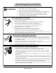
SAFETY PRECAUTIONS AND WARNINGS PLEASE READ BEFORE USING EQUIPMENT WARNING Keep children away from this equipment Protect yourself and others from possible injury Pacemaker wearers should consult with their doctor before operating Read and follow all instructions in this manual before operating All installation, operation, and maintenance procedures are to be performed only by qualified individuals ELECTRIC SHOCK CAN KILL.
WELDING SPARKS CAN CAUSE INJURY, FIRE, OR EXPLOSION Remove all flammable materials from the welding area Always have a charged fire extinguisher available in the welding area When not welding make sure the welding tip is not grounded, this causes a heat build up and possible fire Avoid welding near hydraulic lines, fuel lines, electrical cords, air hoses, or welding guns and cables Sparks and hot metal fly out from the work area when welding, wear approved safety glasses with side shields under a
NOISE CAN DAMAGE HEARING Prolonged noise exposure from welding equipment can cause damage if levels of noise exceed the OSHA standards Wear approved hearing protectors Warn other workers nearby of the high noise level and hazard CALIFORNIA PROPOSITION 65 WARNINGS Welding or cutting equipment produces fumes or gases which contain chemicals known to the State of California to cause birth defects, and in some cases, cancer. (California Health and Safety Code Section 25249.5 et seq.
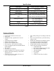
Specifications Rated input 115VAC, 60 hertz, 20 amps Maximum output open-circuit voltage 28 volts DC Rated output 90 AMPS@18volts 20%duty cycle Wire feed rate 59 to 393 in/min (1.5-10.0m/min) Specifications of applicable welding .025”-.030” (0.6-0.8mm) solid steel wire .030”-.035” (0.8-0.9mm) Flux-Cored Welding Wire Spool 8”x2” (200mmx50mm) 4”x2” (100mmx50mm) Weight 54 lb (24.5 kg) Dimensions (Length*Width*Height) 16”x9.6”x14.
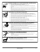
Installation/Setup Safety Considerations Warning Electric Shock Can Kill Only qualified personnel should attempt to install this equipment. Turn off the input power at the power panel or disconnect switch and discharge capacitors before working inside the equipment. Take care not to touch electrically hot parts Make sure the unit is switched off before plugging it into a the power outlet.
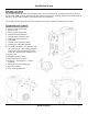
Installation/Setup Selecting A Location The 135WFG Welder should be placed where clean cool air can easily flow through the vents in the front of the unit. Dirt and dust can be drawn into the unit resulting in excessive operating temperatures and shutdowns, therefore, dirt and dust around the unit should be kept to a minimum. The 135WFG Welder should be placed on a stable, level surface suitable to hold the unit’s weight. Components and Controls 1. Output voltage adjust knob 2. Power switch 3.
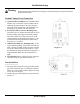
Installation/Setup Warning Always unplug the welder before connecting or disconnecting the Ground Clamp cable and/or the Gun Cable. Ground Clamp & Lead Connection 1. Ground Cable Attachment: The Hot Max MIG Welders use a convenient 1/4 turn connection for attaching the ground cable to the unit. Insert the male end of the ground cable into the female connection port (1) and turn 1/4 turn clockwise. 2.
Installation/Setup Gas Connection Warning Cylinder can explode if damaged. Keep cylinder chained upright to a secure support. Keep cylinder away from areas where it could be damaged. Never lift or move the welder with the cylinder attached. Do not let the welding electrode touch the cylinder. Keep the cylinder away from welding or other live circuits. Shielding Gas may be harmful to health or cause death. Turn off gas supply when not in use. Refer to American National Standard Z-49.
Installation/Setup Gas Hook Up (cont.) 7. Reopen the regulator valve until the flow indicator shows 15 L/min (initial flow setting). The setting may need to be adjusted by the operator to compensate for welding conditions. 8. Always close the cylinder valve and open the regulator valve when not in use. Input Connections The 135WFG welder has power input cables located on the rear of the unit.
Operation Safety Considerations Warning Electric Shock Can Kill Do not touch live electrical parts of the electrode with skin or wet clothing. Insulate yourself from work and ground. Always wear insulated gloves and keep them dry. Fumes & Gases Can Be Hazardous Plasma cutter should only be used in a well ventilated area or with an exhaust system. Keep your head away from the fumes. Arc Rays Can Burn Skin and Eyes Always were eye, ear and body protection.
Operation Controls 1. Output Voltage Control—The Hot Max infinite setting output voltage control knob adjusts to any setting from 25 to 135 amps. Additionally, the voltage can be adjusted while welding. 2. Power On/Off Switch—A light within the switch will be illuminated and the cooling fan will run when the power is on. 3. Speed Control—Controls the wire feed speed. The control can be preset on the dial to the setting specified on the application chart located inside the wire feed section door. 4.
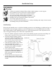
Operation Loading Wire Note: Always tur n power off when wor king inside the welder enclosure. 2 1 8” Diameter Spool 1. Remove the wing nut (5), and plastic tension spacer (6). 3 2. Place the spool adaptor (2) over the shaft as shown. 3. Replace spacer and wing nut. Make sure the wing nut is positioned so that it does not interfere with the locking tab. Use the welding wire board with 8 "(200 mm) in diameter Figure D-1 4.
Operation Wire Feeding 1. Release the spring loaded tension arm (1) by flipping it to the right and down. 2. Lift the idle arm (2). 3. Make sure the grove size on the drive roll (5) is in the feeding position that matches the wire size being used. Refer to the Suggested Settings for Welding chart at the back of this manual or on the inside of the welder compartment door. 4. Detach the end of the wire from the spool and clip a small amount of wire to get a good straight start.
Operation Welding 1. See Suggested Settings at the back of this manual or on the inside of the wire feed compartment door for welding wire and shielding gas recommendations. 2 See Suggested Settings for information on setting the controls on the Hot Max 135WFG for specific welding wire and metal thickness. 3. Set the voltage and wire speed. 4. Insure the unit is set up for the correct polarity for the welding wire and process being used.
Operation Changing Drive Roll The drive roll has two groves; the smaller grove is for .023” - .025” welding wire and the larger grove is for .030” - .035” welding wire. The welder is shipped set up for the larger welding wire sizes. To change the drive roll position: 1. Connect the unit to the appropriate power source. 2. Open the wire drive compartment door, release the spring loaded tension arm (1) by flipping it to the right and down and lift the idle arm (2). 3. Turn the power on. 4.
Maintenance Warning Electrical Shock Can Kill Disconnect from the input power source prior to working inside the Hot Max 135WFG. Allow only qualified personnel to do maintenance and trouble shooting. General Maintenance Power Supply Compartment Gun Cable The Hot Max 135WFG does not have any serviceable parts inside the power supply compartment. Do not attempt to service parts in the power supply compartment.
Troubleshooting Warning Most components of the 135WFG welder are not serviceable by the operator and should only be serviced by a qualified repair technician. Unauthorized repairs to these units may result in danger to the operator and will void the factory warranty. For your safety, please follow all safety precautions found throughout this manual. Problem Possible Cause Nothing happens when the trigger is pulled; no wire feed, weld output or gas flow. Fan is not operating. 1.
Troubleshooting Problem Possible Cause Arc is unstable—Poor starting 1. Check to insure proper input voltage to the welder. 2. Check electrode polarity to make sure it is correct for the process being used. 3. Check tip for proper size and damage; replace if necessary. 4. Insure proper gas flow for the process. 5. Make sure the connections for the ground cable are correct. 6. Make sure the drive roll is installed and aligned properly. 7.
Warranty KDAR Company, and its affiliates, warrants that all welders covered under this warranty is free from defects in material and workmanship for one year from the date of purchase. KDAR also warrants that all guns, hoses and ground clamp assemblies are free from defects in material and workmanship for 90 days from the date of purchase. This warranty is extended to the original purchaser who uses the product in a consumer application (personal, residential or household usage).