
User's Manual


Table Of Contents
- CONTENTS
- I. Specifications
- 1. Icemaker
- KM-1300SAH
- KM-1300SWH
- KM-1300SRH
- KM-1300SAH3
- KM-1300SWH3
- KM-1300SRH3
- 2. Condensing Unit
- URC-12F
- II. General Information
- 1. Construction
- [a] KM-1300SAH, KM-1300SAH3
- [b] KM-1300SWH, KM-1300SWH3
- [c] KM-1300SRH, KM-1300SRH3
- 2. Controller Board
- [a] Solid-State Control
- [b] Controller Board
- [c] Sequence
- [d] Controls and Adjustments
- [e] Checking the Controller Board
- III. Technical Information
- 1. Water Circuit and Refrigerant Circuit
- [a] KM-1300SAH, KM-1300SAH3
- [b] KM-1300SWH, KM-1300SWH3
- [c] KM-1300SRH, KM-1300SRH3
- 2. Wiring Diagrams
- [a] KM-1300SAH, KM-1300SWH
- [b] KM-1300SRH
- [c] KM-1300SAH3, KM-1300SWH3
- [d] KM-1300SRH3
- 3. Timing Chart
- 4. Performance Data
- [a] KM-1300SAH
- [b] KM-1300SWH
- [c] KM-1300SRH
- [d] KM-1300SAH3
- [e] KM-1300SWH3
- [f] KM-1300SRH3
- IV. Service Diagnosis
- 1. No Ice Production
- 2. Evaporator is Frozen Up
- 3. Low Ice Production
- 4. Abnormal Ice
- 5. Other
- V. Removal and Replacement of Components
- 1. Service for Refrigerant Lines
- [a] Refrigerant Recovery
- [b] Evacuation and Recharge [R-404A]
- 2. Brazing
- 3. Removal and Replacement of Compressor
- 4. Removal and Replacement of Drier
- 5. Removal and Replacement of Expansion Valve
- 6. Removal and Replacement of Hot Gas Valve and Line Valve
- 7. Removal and Replacement of Evaporator
- 8. Removal and Replacement of Water Regulating Valve - Water-Cooled Model Only
- 9. Adjustment of Water Regulating Valve - Water-Cooled Model Only
- 10. Removal and Replacement of Condensing Pressure Regulator (C.P.R.) -
- 11. Removal and Replacement of Thermistor
- 12. Removal and Replacement of Fan Motor
- 13. Removal and Replacement of Water Valve
- 14. Removal and Replacement of Pump Motor
- 15. Removal and Replacement of Spray Tubes
- VI. Maintenance and Cleaning Instructions
- 1. Preparing the Icemaker for Long Storage
- 2. Cleaning and Sanitizing Procedures
- [a] Cleaning Procedure
- [b] Sanitizing Procedure - Following Cleaning Procedure
- 3. Maintenance
59
11. Removal and Replacement of Thermistor
CAUTION
1. Fragile, handle very carefully.
2. Always use a recommended sealant (high thermal conductive type), Model
KE4560RTV manufactured by Shinetsu Silicone, Part Code 60Y000-11, or Part
Code 4A0683-01 equivalent.
3. Always use a recommended foam insulation (non-absorbent type) or equivalent.
1) Turn off the power supply.
2) Remove the panels.
3) Remove the control box cover.
4) Disconnect the thermistor leads from
the K3 connector on the controller board.
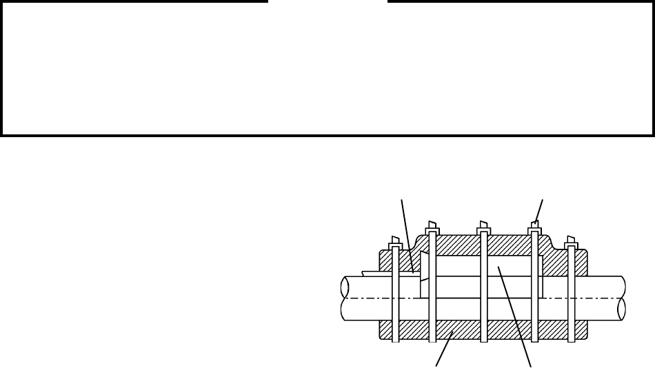
5) Remove the plastic cable ties, foam
insulation, thermistor holder and
thermistor. See Fig. 2.
6) Scrape away the old sealant on the
thermistor holder and the suction pipe.
7) Wipe off moisture or condensation on the suction pipe.
8) Smoothly apply recommended sealant (KE4560RTV, Part Code 60Y000-11 or
4A0683-01) to the thermistor holder concave.
9) Attach the new thermistor to the suction pipe very carefully to prevent damage to
the leads. And secure it using the thermistor holder and recommended foam
insulation.
10) Secure the insulation using the plastic cable ties.
11) Connect the thermistor leads through the bushing of the control box to the K3 connector on the
controller board.
Note: Do not cut the leads of the thermistor while installing it.
12) Replace the control box cover and the panels in their correct positions.
13) Turn on the power supply.
Foam Insulation Thermistor Holder
Thermistor Lead Cable Tie
Fig. 2