
User's Manual


Table Of Contents
- CONTENTS
- I. Specifications
- 1. Icemaker
- KM-1300SAH
- KM-1300SWH
- KM-1300SRH
- KM-1300SAH3
- KM-1300SWH3
- KM-1300SRH3
- 2. Condensing Unit
- URC-12F
- II. General Information
- 1. Construction
- [a] KM-1300SAH, KM-1300SAH3
- [b] KM-1300SWH, KM-1300SWH3
- [c] KM-1300SRH, KM-1300SRH3
- 2. Controller Board
- [a] Solid-State Control
- [b] Controller Board
- [c] Sequence
- [d] Controls and Adjustments
- [e] Checking the Controller Board
- III. Technical Information
- 1. Water Circuit and Refrigerant Circuit
- [a] KM-1300SAH, KM-1300SAH3
- [b] KM-1300SWH, KM-1300SWH3
- [c] KM-1300SRH, KM-1300SRH3
- 2. Wiring Diagrams
- [a] KM-1300SAH, KM-1300SWH
- [b] KM-1300SRH
- [c] KM-1300SAH3, KM-1300SWH3
- [d] KM-1300SRH3
- 3. Timing Chart
- 4. Performance Data
- [a] KM-1300SAH
- [b] KM-1300SWH
- [c] KM-1300SRH
- [d] KM-1300SAH3
- [e] KM-1300SWH3
- [f] KM-1300SRH3
- IV. Service Diagnosis
- 1. No Ice Production
- 2. Evaporator is Frozen Up
- 3. Low Ice Production
- 4. Abnormal Ice
- 5. Other
- V. Removal and Replacement of Components
- 1. Service for Refrigerant Lines
- [a] Refrigerant Recovery
- [b] Evacuation and Recharge [R-404A]
- 2. Brazing
- 3. Removal and Replacement of Compressor
- 4. Removal and Replacement of Drier
- 5. Removal and Replacement of Expansion Valve
- 6. Removal and Replacement of Hot Gas Valve and Line Valve
- 7. Removal and Replacement of Evaporator
- 8. Removal and Replacement of Water Regulating Valve - Water-Cooled Model Only
- 9. Adjustment of Water Regulating Valve - Water-Cooled Model Only
- 10. Removal and Replacement of Condensing Pressure Regulator (C.P.R.) -
- 11. Removal and Replacement of Thermistor
- 12. Removal and Replacement of Fan Motor
- 13. Removal and Replacement of Water Valve
- 14. Removal and Replacement of Pump Motor
- 15. Removal and Replacement of Spray Tubes
- VI. Maintenance and Cleaning Instructions
- 1. Preparing the Icemaker for Long Storage
- 2. Cleaning and Sanitizing Procedures
- [a] Cleaning Procedure
- [b] Sanitizing Procedure - Following Cleaning Procedure
- 3. Maintenance
23
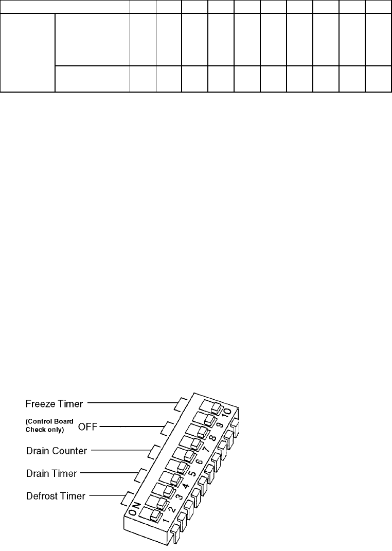
[d] Controls and Adjustments
The dip switch is factory-adjusted to the following positions:
Switch Nos. 1 and 2:
Used for adjustment of the defrost timer. The defrost timer starts counting when the thermistor
reads a certain temperature at the evaporator outlet.
Switch Nos. 3 and 4:
Used for adjustment of the drain timer. When a freeze cycle is completed, the pump motor
stops, and the icemaker resumes operation in 2 seconds. Then the pump motor drains the
water tank for the time determined by the drain timer. The drain timer also determines the time
to restrain completion of a defrost cycle, i.e. the minimum defrost time.
Switch Nos. 5 and 6:
Used for adjustment of the drain counter. The pump motor drains the water tank at the
frequency determined by the drain counter.
Switch Nos. 7 and 8:
Used only for checking the controller board. Usually set in OFF position.
Switch Nos. 9 and 10:
Used for adjustment of freeze timer.
The freeze timer determines maximum
freeze cycle time. Upon termination of
freeze timer, machine initiates the
harvest cycle. After 2 consecutive timer
terminations, machine will shut down,
possibly indicating a problem.
12345678910
2A1410-01 KM-1300SAH
KM-1300SWH
KM-1300SRH
KM-1300SWH3
KM-1300SAH3
KM-1300SRH3
DIP SWITCH NO.
OFF OFF ON
ON ON OFF
ON ON ON OFF
OFF OFF ON ON OFF ON OFF
OFF OFF OFF