
User's Manual


Table Of Contents
- CONTENTS
- I. Specifications
- 1. Icemaker
- KM-1300SAH
- KM-1300SWH
- KM-1300SRH
- KM-1300SAH3
- KM-1300SWH3
- KM-1300SRH3
- 2. Condensing Unit
- URC-12F
- II. General Information
- 1. Construction
- [a] KM-1300SAH, KM-1300SAH3
- [b] KM-1300SWH, KM-1300SWH3
- [c] KM-1300SRH, KM-1300SRH3
- 2. Controller Board
- [a] Solid-State Control
- [b] Controller Board
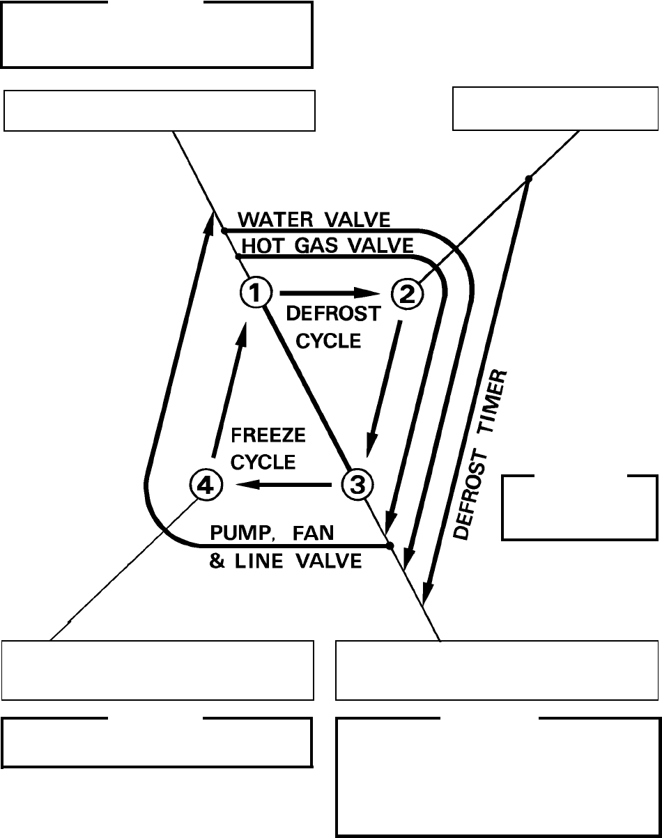
- [c] Sequence
- [d] Controls and Adjustments
- [e] Checking the Controller Board
- III. Technical Information
- 1. Water Circuit and Refrigerant Circuit
- [a] KM-1300SAH, KM-1300SAH3
- [b] KM-1300SWH, KM-1300SWH3
- [c] KM-1300SRH, KM-1300SRH3
- 2. Wiring Diagrams
- [a] KM-1300SAH, KM-1300SWH
- [b] KM-1300SRH
- [c] KM-1300SAH3, KM-1300SWH3
- [d] KM-1300SRH3
- 3. Timing Chart
- 4. Performance Data
- [a] KM-1300SAH
- [b] KM-1300SWH
- [c] KM-1300SRH
- [d] KM-1300SAH3
- [e] KM-1300SWH3
- [f] KM-1300SRH3
- IV. Service Diagnosis
- 1. No Ice Production
- 2. Evaporator is Frozen Up
- 3. Low Ice Production
- 4. Abnormal Ice
- 5. Other
- V. Removal and Replacement of Components
- 1. Service for Refrigerant Lines
- [a] Refrigerant Recovery
- [b] Evacuation and Recharge [R-404A]
- 2. Brazing
- 3. Removal and Replacement of Compressor
- 4. Removal and Replacement of Drier
- 5. Removal and Replacement of Expansion Valve
- 6. Removal and Replacement of Hot Gas Valve and Line Valve
- 7. Removal and Replacement of Evaporator
- 8. Removal and Replacement of Water Regulating Valve - Water-Cooled Model Only
- 9. Adjustment of Water Regulating Valve - Water-Cooled Model Only
- 10. Removal and Replacement of Condensing Pressure Regulator (C.P.R.) -
- 11. Removal and Replacement of Thermistor
- 12. Removal and Replacement of Fan Motor
- 13. Removal and Replacement of Water Valve
- 14. Removal and Replacement of Pump Motor
- 15. Removal and Replacement of Spray Tubes
- VI. Maintenance and Cleaning Instructions
- 1. Preparing the Icemaker for Long Storage
- 2. Cleaning and Sanitizing Procedures
- [a] Cleaning Procedure
- [b] Sanitizing Procedure - Following Cleaning Procedure
- 3. Maintenance
22
2nd Cycle and after with no pump drain
IMPORTANT
Freeze cycle time is limited by the freeze timer
factory setting even if the Float Switch does
not open.
1. Float Switch opens and signals to complete
freeze cycle.
2. Thermistor reads 48° F.
Defrost Timer starts counting.
IMPORTANT
Water Valve
opening is limited to 6
minutes.
4. After the first 5 minutes in freeze cycle.
Ready to complete freeze cycle when Float
Switch circuit opens.
3. Defrost Timer stops counting.
Defrost cycle is completed and freeze cycle
starts.
IMPORTANT
Board never accepts freeze completion signal
within the first 5 minutes in freeze cycle.
IMPORTANT
1. Board never accepts defrost completion
signal within the first 2 minutes in defrost
cycle.
2. Defrost cycle time is limited to 20 minutes
even if Defrost Timer does not stop counting.