
User's Manual


Table Of Contents
- CONTENTS
- I. Specifications
- 1. Icemaker
- KM-1300SAH
- KM-1300SWH
- KM-1300SRH
- KM-1300SAH3
- KM-1300SWH3
- KM-1300SRH3
- 2. Condensing Unit
- URC-12F
- II. General Information
- 1. Construction
- [a] KM-1300SAH, KM-1300SAH3
- [b] KM-1300SWH, KM-1300SWH3
- [c] KM-1300SRH, KM-1300SRH3
- 2. Controller Board
- [a] Solid-State Control
- [b] Controller Board
- [c] Sequence
- [d] Controls and Adjustments
- [e] Checking the Controller Board
- III. Technical Information
- 1. Water Circuit and Refrigerant Circuit
- [a] KM-1300SAH, KM-1300SAH3
- [b] KM-1300SWH, KM-1300SWH3
- [c] KM-1300SRH, KM-1300SRH3
- 2. Wiring Diagrams
- [a] KM-1300SAH, KM-1300SWH
- [b] KM-1300SRH
- [c] KM-1300SAH3, KM-1300SWH3
- [d] KM-1300SRH3
- 3. Timing Chart
- 4. Performance Data
- [a] KM-1300SAH
- [b] KM-1300SWH
- [c] KM-1300SRH
- [d] KM-1300SAH3
- [e] KM-1300SWH3
- [f] KM-1300SRH3
- IV. Service Diagnosis
- 1. No Ice Production
- 2. Evaporator is Frozen Up
- 3. Low Ice Production
- 4. Abnormal Ice
- 5. Other
- V. Removal and Replacement of Components
- 1. Service for Refrigerant Lines
- [a] Refrigerant Recovery
- [b] Evacuation and Recharge [R-404A]
- 2. Brazing
- 3. Removal and Replacement of Compressor
- 4. Removal and Replacement of Drier
- 5. Removal and Replacement of Expansion Valve
- 6. Removal and Replacement of Hot Gas Valve and Line Valve
- 7. Removal and Replacement of Evaporator
- 8. Removal and Replacement of Water Regulating Valve - Water-Cooled Model Only
- 9. Adjustment of Water Regulating Valve - Water-Cooled Model Only
- 10. Removal and Replacement of Condensing Pressure Regulator (C.P.R.) -
- 11. Removal and Replacement of Thermistor
- 12. Removal and Replacement of Fan Motor
- 13. Removal and Replacement of Water Valve
- 14. Removal and Replacement of Pump Motor
- 15. Removal and Replacement of Spray Tubes
- VI. Maintenance and Cleaning Instructions
- 1. Preparing the Icemaker for Long Storage
- 2. Cleaning and Sanitizing Procedures
- [a] Cleaning Procedure
- [b] Sanitizing Procedure - Following Cleaning Procedure
- 3. Maintenance
20
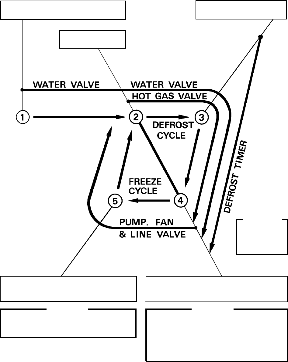
4. Defrost Timer stops counting.
Defrost cycle is completed and freeze cycle
starts.
[c] Sequence
1st Cycle
1. Unit energized and Control Switch to “ICE”
position. Water supply cycle starts.
2. After 1 minute.
Defrost cycle starts.
IMPORTANT
Water Valve
opening is limited
to 6 minutes.
5. After the first 5 minutes in freeze cycle.
Ready to complete freeze cycle when Float
Switch circuit opens.
IMPORTANT
1. Board never accepts defrost completion signal
within the first 2 minutes in defrost cycle.
2. Defrost cycle time is limited to 20 minutes even
if Defrost Timer does not stop counting.
3. Thermistor reads 48°F.
Defrost Timer starts counting.
IMPORTANT
Board never accepts freeze completion signal
within the first 5 minutes in freeze cycle.