Hoshizaki Hoshizaki America, Inc. Modular Crescent Cuber Models KM-320MAH, MWH KM-515MAH, MWH, MRH KM-600MAH KM-650MAH, MWH(-M), MRH KM-901MAH, MWH, MRH/3 “A Superior Degree of Reliability” SERVICE MANUAL www.hoshizaki.
WARNING Only qualified service technicians should install and service the appliance. To obtain the name and phone number of your local Hoshizaki Certified Service Representative, visit www.hoshizaki.com. No service should be undertaken until the technician has thoroughly read this Service Manual. Failure to service and maintain the appliance in accordance with this manual will adversely affect safety, performance, component life, and warranty coverage.
IMPORTANT This manual should be read carefully before the appliance is serviced. Read the warnings and guidelines contained in this manual carefully as they provide essential information for the continued safe use, service, and maintenance of the appliance. Retain this manual for any further reference that may be necessary. CONTENTS Important Safety Information.................................................................................................. 6 I.
5. Bin Control Selector or Harvest Pump Timer Operation (S4 dip switch 7).............. 48 6. Factory Use (S4 dip switch 8)................................................................................. 49 7. Freeze Timer (S4 dip switch 9 & 10)........................................................................ 49 8. Float Switch Selector (S5 dip switch 1): "G" Control Board.................................... 50 9. Refill Counter (S5 dip switch 2 through 5): "G" Control Board.........................
C. Wiring Diagrams .......................................................................................................... 87 1. Diagrams Without Harvest Pump Timer Relays...................................................... 87 a) KM-320M_H, KM-515M_H, KM-600MAH......................................................... 87 b) KM-650MAH, KM-650MWH, KM-901MAH, KM-901MWH................................ 88 c) KM-650MRH, KM-901MRH...............................................................................
Important Safety Information Throughout this manual, notices appear to bring your attention to situations which could result in death, serious injury, damage to the appliance, or damage to property. WARNING Indicates a hazardous situation which could result in death or serious injury. NOTICE Indicates a situation which could result in damage to the appliance or property. IMPORTANT Indicates important information about the use and care of the appliance.
WARNING, continued • The appliance is not intended for use by persons (including children) with reduced physical, sensory, or mental capabilities, or lack of experience and knowledge, unless they have been given supervision or instruction concerning use of the appliance by a person responsible for their safety. • Children should be properly supervised around this appliance. • Do not climb, stand, or hang on the appliance or allow children or animals to do so.
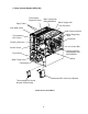
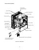
I. Construction and Water/Refrigeration Circuit Diagram A. Construction 1.
2.
3.
B. Water/Refrigeration Circuit Diagram 1.
2.
3. Remote Models (MRH/3) Condenser Fan Headmaster (C.P.R.
Comp energized FMR energized HGV energized WV energized FS closed Thermistor in control 14 Legend: Comp–compressor FM–fan motor FMR–fan motor-remote FS–float switch HGV–hot gas valve LLV–liquid line valve PM–pump motor WV–inlet water valve FS opens or freeze timer terminates FS in control Comp continues FMR continues HGV energized WV energized (KM-320M_H S4 dip switch 3 & 4) PM de-energizes for 2 sec., then reverses for 10/20 sec.
2. Icemaker Off TBC closed No ice touching TBC bulb. Icemaker starts at "1. 1-Minute Fill Cycle." 3. Ice Level Lowered Legend: MBC–mechanical bin control TBC–themostatic bin control MBC Operation Shutdown and Restart MBC open (MBC actuator paddle engaged) Green "BC CLOSED" LED off Yellow "BC OPEN" LED on All components de-energized. Yellow "BC OPEN" LED continues. All components de‑energized. Shutdown Delay: • Fill Cycle–15 sec. after activation.
Comp energized FMR energized HGV energized WV energized FS closed Thermistor in control Thermistor temperature reaches 48°F (9°C) (3.9 kΩ or less). Harvest timer starts (1 to 3 min.). FS open 16 Yellow "BC OPEN" LED continues. All components de‑energized. To 1 above MBC closed (MBC actuator paddle disengaged) Green "BC CLOSED" LED on Yellow "BC OPEN" LED off Icemaker starts at "1. 1-Minute Fill Cycle." 3. Ice Level Lowered Comp continues FMR continues HGV energized PM de-energizes for 2 sec.
B. Service Diagnosis WARNING • The appliance should be diagnosed and repaired only by qualified service personnel to reduce the risk of death, electric shock, serious injury, or fire. • Risk of electric shock. Control switch in "OFF" position does not de‑energize all loads Use extreme caution and exercise safe electrical practices. • Moving parts (e.g., fan blade) can crush and cut. Keep hands clear.
1. "E" and "G" Control Board without Harvest Pump Timer Diagnosis 3) Power On: Turn on the power supply, then move the control switch to the "ICE" position. A 5‑sec. delay occurs. • "E" Control Board: CB red "POWER OK" LED turns on. • "G" Control Board: CB red "POWER OK" LED and green "BC CLOSED" LED turn on. Note: • CB red "POWER" LED remains on unless the 10.5VAC power supply is interrupted (K2 connector). • Check CB using the steps in "II.C. Control Board Check.
4) 1-Minute Fill Cycle – LED 4 is on. WV energizes. After 1 min., CB checks for a closed FS. If FS is closed, harvest cycle begins. If harvest cycle begins (Comp, HGV, and FMR energize), continue to step 5. If FS is open, WV remains energized through additional 1‑min. fill cycles until water enters the water tank and FS closes (low water safety protection during initial start up and at the end of each harvest). Diagnosis: Check that water enters the water tank.
e) Initial Harvest Cycle Termination Diagnosis: When the thermistor reaches 48°F (9°C), CB reads 3.9 kΩ from the thermistor and turns harvest termination over to the harvest timer (S4 dip switch 1 & 2). Check discharge line temperature. For a thermistor check, see "II.F. Thermistor Check." If 1-min. fill cycle starts after harvest timer terminates, check that FS is clean and operating properly, see "II.E. Float Switch Check and Cleaning." If FS is closed, CB proceeds to the next cycle. If not, replace CB.
d) PM Diagnosis: Confirm water is flowing over evaporator from PM and not WV. If PM de-energizes once freeze begins, check for 115VAC at CB K1 #4 (R) to neutral (W). If 115VAC is not present, replace CB. If 115VAC is present and PM is de-energized, check for 115VAC at control switch #5 (R) to neutral (W). If 115VAC is present at CB K1 #4 (R) and not at control switch #5 (R), check control switch continuity between #5 (R) and #4 (R). Replace as needed.
7) Pump-Out Cycle – LEDs 1, 3, and 2 are on (10/20 second pump-out). Timing of the first pump-out is dependent on CB. "E" CB first pump‑out is after the first freeze cycle. "G" CB first pump-out is determined by S4 dip switch 5 & 6. See the table below. "E" & "G" Control Board Settings S4 Dip Switch Setting 1st Pump-Out Pump-Out Frequency "E" Control Board "G" Control Board After 1st freeze cycle After 2nd freeze cycle No. 5 No.
9) Shutdown a) "E" Control Board: Thermostatic Bin Control (TBC): When the appliance is running, hold ice in contact with the thermostatic bulb. TBC switch opens within 10 sec., shutting down the appliance. TBC is factory set, and generally no adjustment is required. However, adjustment may be needed in some conditions, particularly at higher altitude locations. NOTICE! Do not adjust S4 dip switch 7 out of the factory default position.
2. "G" Control Board with Harvest Pump Timer Diagnosis 3) Power On: Turn on the power supply, then move the control switch to the "ICE" position. A 5‑sec. delay occurs. CB red "POWER OK" LED and green "BC CLOSED" LED turn on. If yellow "BC OPEN" LED is on (indicating a full bin), check MBC. Move ice away from MBC actuator paddle. If yellow "BC OPEN" LED stays on, see "II.D.2. Mechanical Bin Control (MBC) Check." Note: • CB red "POWER OK" LED remains on unless the 10.
4) 1-Min. Fill Cycle – LED 4 is on. WV and X11 relay energize. After 1 min., CB checks for a closed FS. If FS is closed, the harvest cycle begins. If harvest cycle begins (Comp, HGV, FMR energized), continue to step 5a. If FS is open, WV remains energized through additional 1-min. fill cycles until water enters the water tank and FS closes (low water safety protection during initial start up and at the end of each harvest). Diagnosis: Check that water enters the water tank.
5b) Harvest Pump Timer – LEDs 1, 3, and 2 are on. When the thermistor reaches 48°F (9°C), CB reads 3.9 kΩ from the thermistor and turns harvest termination over to the harvest timer (S4 dip switch 1 & 2). 50 sec. before the harvest timer terminates, LED 3 turns on and PM energizes. Comp, FMR, HGV, and X10 relay continue. LED 4 turns off, WV and X11 relay de‑energize. Diagnosis: Place a thermometer on the suction line next to the thermistor. Has it warmed to 48°F (9°C) or warmer? Confirm thermistor status.
6) Freeze Cycle – LED 1 is on. Comp, FMR, and PM continue. FM and LLV energize. HGV and X10 relay de‑energize. Appliance is held in freeze by a 5-min. short cycle protection timer. After 5-min. timer terminates and FS opens, freeze cycle terminates. Note: PM power supply switches from CB K1 #5 (DBU) in harvest to K1 #4 (R) in freeze. a) Freeze Cycle Diagnosis: Confirm Comp, FMR, and PM continue. Confirm that FM and LLV energize. Confirm WRV opens. Next, confirm HGV and X10 relay de-energize.
f) Refrigerant Pressures, HM, and TXV Diagnosis: If evaporator is still not cooling, check refrigerant pressures. See "VIII.B. Performance Data." Next, check HM operation. If refrigeration pressures are above HM setpoint and HM is bypassing, replace HM. Check TXV for proper operation. Remove TXV bulb and hold it in your hand, refrigerant low-side pressure should rise, place TXV bulb in ice water, refrigerant low-side pressure should drop.
is complete. The pump-out frequency control (S4 dip switch 5 & 6) is factory set, and generally no adjustment is required. However, the pump‑out frequency control can be set to have a pump-out occur every cycle, or every 2, 5, or 10 cycles. For details, see "III.C.4. Pump‑Out Frequency Control (S4 dip switch 5 & 6)." Pump-Out Diagnosis: In the freeze cycle before pump-out (see table above), after 5 min. of freeze disconnect CB black K5 connector (FS connector).
C. Control Board Check Before replacing CB that does not show a visible defect and that you suspect is bad, always conduct the following check procedure. This procedure will help you verify your diagnosis. Alarm Reset: If CB is in alarm (beeping), press the "ALARM RESET" button on CB while CB is beeping. WARNING! Risk of electric shock. Care should be taken not to touch live terminals. Once reset, the icemaker starts at the 1-minute fill cycle. For audible alarm information, see "III.B.
D. Bin Control Check 1. Thermostatic Bin Control Check TBC shuts down the icemaker within 10 sec. when ice contacts the thermostatic bulb, regardless of the cycle at activation. NOTICE When the ambient temperature is below 45°F (7°C), TBC opens and shuts down the appliance even if the ice storage bin is empty. When BC is set in the prohibited range, the appliance operates continuously even if the ice storage bin is filled with ice.
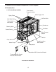
2. Mechanical Bin Control Check and Cleaning a) Mechanical Bin Control Check This appliance uses a lever-actuated proximity switch to control the ice level in the storage bin. No adjustment is required. To check TBC, follow the steps below. 1) Turn off the power supply. 2) Remove the front panel, then move the control switch to the "OFF" position. 3) Remove the control box cover and base cover, then clear any ice away from MBC. 4) Check MBC wire harness connections. See Fig. 1.
b) Mechanical Bin Control Cleaning Scale may build up on MBC. Scale can cause the actuator paddle and magnet to stick. In this case, MBC should be cleaned. WARNING CHOKING HAZARD: Ensure all components, fasteners, and thumbscrews are securely in place after the icemaker is serviced. Make sure that none have fallen into the dispense unit/ice storage bin. 1) Turn off the power supply. 2) Remove the front panel and base cover, then move the control switch to the "OFF" position. 3) Clear any ice away from MBC.
E. Float Switch Check and Cleaning FS is used to determine that there is sufficient water in the water tank after the 1‑min. fill cycle and after each harvest cycle. FS is also used to determine that the appropriate volume of water has been converted into ice before switching out of the freeze cycle. No adjustment is required. 1. Float Switch Check To check FS, follow the steps below. 1) Turn off the power supply. 2) Remove the front panel, then move the control switch to the "OFF" position.
2. Float Switch Cleaning Depending on local water conditions, scale may build up on FS. Scale on the switch can cause the float to stick. In this case, FS should be cleaned. 1) Turn off the power supply. 2) Remove the front panel, then move the control switch to the "OFF" position. 3) Remove the base cover, then disconnect one end of the pump tubing to drain the water tank. See Fig. 3. After the water tank has drained, reconnect the pump tubing.
F. Thermistor Check To check thermistor resistance, follow the steps below. 1) Turn off the power supply. 2) Remove the front panel. Move the control switch to the "OFF" position. 3) Remove the control box cover. 4) Remove the thermistor from the refrigerant tubing. 5) Immerse the thermistor sensor portion in a glass containing ice and water for 2 or 3 min. 6) Disconnect the thermistor connector from CB K3 connector and check the resistance between thermistor leads. Normal range is 4.7 to 6.2 kΩ.
G. Diagnostic Tables 1. No Ice Production No Ice Production - Possible Cause 1. Power Supply a) Off, blown fuse, or tripped breaker. b) Not within specifications. 2. Main Transformer (3 phase and KM-650MWH-M only) (208/230VAC/115VAC) a) Voltage tap switch not set to proper voltage. 3. Fuse (Control Box) a) Blown. 4. Thermostatic Bin Control See "II.D. Bin Control Check" a) Tripped with bin filled with ice. b) Coil winding open or shorted. b) Ambient temperature too cool. c) Set too warm.
No Ice Production - Possible Cause 15. Thermistor See "II.F. Thermistor Check" a) Loose, disconnected, or defective. 16. Pump Motor a) Motor winding open. b) Bearing worn out or locked rotor. c) Defective capacitor. d) Mechanical seal worn out. 17. Thermostatic Expansion Valve a) Bulb loose. b) Operating erratically. 18. Liquid Line Valve a) Closed in freeze cycle. b) Open in harvest cycle. 19. Fan Motor a) Motor winding open. b) Bearing worn out or locked rotor. c) Defective capacitor. 20.
Freeze-Up - Possible Cause 11. Thermostatic Expansion Valve a) Defective. 12. Hot Gas Valve a) Closed or restricted. 13. Liquid Line Valve a) Open. Freeze Cycle 1. Evaporator a) Scaled up. b) Damaged. 2. Spray Tubes and/or Spray Guides a) Dirty. 3. Refrigerant Charge a) Low. 4. Control Board See "II.C. Control Board Check" a) Freeze timer (S4 dip switch 9 & 10) set incorrectly. 5. Inlet Water Valve a) Leaking by. 6. Float Switch See "II.E.
Low Ice Production - Possible Cause Long Freeze Cycle 1. Evaporator a) Scaled up, dirty. 2. Float Switch See "II.E. Float Switch Check and Cleaning" a) Scaled up, dirty. 3. Inlet Water Valve a) Leaking by. 4. Hot Gas Valve a) Erratic or open. 5. Condenser a) Clogged. 6. Control Board See "II.C. Control Board Check" a) Float switch connection loose (K5). 7. Refrigerant Charge a) Low. 8. Thermostatic Expansion Valve a) Bulb loose. b) Float sticking. c) Defective switch. b) Defective.
III. Controls and Adjustments • A Hoshizaki exclusive control board is employed in KM series appliances. • All models are pretested and factory adjusted. • For a control board check procedure, see "II.C. Control Board Check." NOTICE • Fragile, handle very carefully. • The control board contains integrated circuits, which are susceptible to failure due to static discharge. It is especially important to touch the metal part of the icemaker when handling or replacing the control board.
A. Control Board Layout 1. "E" Control Board "E" Control Board • "ALARM RESET" Button • "OUTPUT TEST" Button (used to test relays on control board) • S4 Dip Switch • Freeze Timer LED (yellow) • K3 (white) Connector Thermistor (harvest control and high temperature safety) • Harvest Backup Timer LED (orange) • K4 (red) Connector Open • Alarm Buzzer • Part Number • POWER OK LED (red) (lights when 10.
2.
B. LED Lights and Audible Alarm Safeties 1. "E" Control Board At startup, a 5-second delay occurs while the control board conducts an internal timer check. A beep occurs when power is turned off. The red "POWER OK" LED indicates proper control voltage and remains on unless a control voltage problem occurs. The green LEDs 1 through 4 energize and sequence from initial startup as listed in the table below. Note that the order of the LEDs from the outer edge of the control board is 1, 4, 3, 2.
2. "G" Control Board At startup, a 5-second delay occurs while the control board conducts an internal timer check. A beep occurs when the control switch is moved to the "ICE" position. The red "POWER OK" LED indicates proper control voltage and remains on unless a control voltage problem occurs. The green LEDs 1 through 4 energize and sequence from initial startup as listed in the table below. Note that the order of the LEDs from the outer edge of the control board is 1, 4, 3, 2.
C. Settings and Adjustments NOTICE Dip switches are factory set. Failure to maintain factory settings may adversely affect performance and warranty coverage. For more information, contact your Hoshizaki Service Center. 1. Default Dip Switch Settings The dip switches are factory-adjusted to the following positions for both the "E" and "G" control boards: a) "E" and "G" Control Board without Harvest Pump Timer Operation "E" Control Board S4 Dip Switch No.
2. Harvest Timer (S4 dip switch 1 & 2) The harvest timer starts counting when the thermistor reaches 48°F (9°C) at the evaporator outlet and the control board reads 3.9 kΩ from the thermistor. The harvest timer is factory set, and generally no adjustment is required. However, a setting longer than the factory setting may be advised in cases where the drain provided at harvest needs to be prolonged for extra cleaning.
4. Pump-Out Frequency Control (S4 dip switch 5 & 6) NOTICE Do not adjust on KM-515M_H without harvest pump timer. Adjustments to this setting on KM-515M_H without harvest pump timer may adversely affect performance and warranty coverage. The pump-out frequency control is factory set to drain the water tank every 10 cycles on all KM-320M_H, KM-600MAH, KM-650M_H, KM-901M_H/3 and on KM-515MAH with harvest pump timer, and every cycle on KM-515M_H without harvest pump timer. Generally no adjustment is required.
(2) Harvest Pump Timer, "G" Control Board NOTICE Factory set for proper operation. Do not adjust. Adjustment outside of the factory default setting may result in damage to the appliance. Depending on the harvest pump timer setting, the pump motor either stays off or is energized the last 50 seconds of harvest. When the pump motor is energized, water circulates over the evaporator.
8. Float Switch Selector (S5 dip switch 1): "G" Control Board NOTICE Do not adjust. This must be left in the factory default position or the icemaker will not operate correctly. 9. Refill Counter (S5 dip switch 2 through 5): "G" Control Board NOTICE Do not adjust. These must be left in the factory default position or the icemaker will not operate correctly. D.
IV. Refrigeration Circuit and Component Service Information WARNING • This appliance should be diagnosed and repaired only by qualified service personnel to reduce the risk of death, electric shock, serious injury, or fire. • Move the control switch to the "OFF" position and turn off the power supply. Place the disconnect in the "OFF" position. Lockout/Tagout to prevent the power supply from being turned back on inadvertently.
2. Brazing WARNING • R-404A itself is not flammable at atmospheric pressure and temperatures up to 176°F (80°C). • R-404A itself is not explosive or poisonous. However, when exposed to high temperatures (open flames), R-404A can be decomposed to form hydrofluoric acid and carbonyl fluoride both of which are hazardous. • Do not use silver alloy or copper alloy containing arsenic. 1) Braze all fittings while purging with nitrogen gas flowing at a pressure of 3 to 4 PSIG.
5) Disconnect the gauge manifold hose from the vacuum pump and attach it to a refrigerant service cylinder. Remember to loosen the connection and purge the air from the hose. For the required refrigerant charge, see the rating label inside the icemaker. Hoshizaki recommends only virgin refrigerant or reclaimed refrigerant which meets ARI Standard 700 (latest edition) be used. 6) A liquid charge is required when charging an R-404A system (to prevent fractionation).
B. Component Service Information NOTICE When replacing a component listed below, see the notes to help ensure proper operation. Component Compressor Notes 1 phase: Install a new start capacitor, run capacitor, and start relay. 3 phase: Install a new magnetic contactor. Thermostatic • Attach the thermostatic expansion valve bulb to the suction line in the same location as Expansion Valves the previous bulb. • The bulb should be between the 10 and 2 o'clock positions on the tube.
V. Maintenance The maintenance schedule below is a guideline. More frequent maintenance may be required depending on water quality, the appliance's environment, and local sanitation regulations WARNING • Only qualified service technicians should service the appliance. • To reduce the risk of electric shock, do not touch the control switch or service switch with damp hands • Before servicing: Move the control switch to the "OFF" position and turn off the power supply.
VI. Preparing the Appliance for Periods of Non-Use NOTICE • When storing the appliance for an extended time or in sub-freezing temperatures, follow the instructions below to prevent damage. • To prevent damage to the water pump, do not operate the appliance with the control switch in the "WASH" position when the water tank is empty. When the appliance is not used for two or three days under normal conditions, it is sufficient to move the control switch to the "OFF" position.
3. On water-cooled model, remove the water from the water-cooled condenser: 1) Make sure the power supply is off, then remove the front panel and right side panel. 2) Close the condenser water supply line shut-off valve. If connected to a closed loop system, also close the condenser return line shut-off valve. 3) Open the condenser water supply line drain valve. If connected to a closed loop system, also open the condenser return line drain valve.
VII. Disposal The appliance contains refrigerant and must be disposed of in accordance with applicable national, state, and local codes and regulations. Refrigerant must be recovered by properly certified service personnel.
VIII. Technical Information A. Specification Sheets 1. KM-320MAH AC SUPPLY VOLTAGE AMPERAGE MINIMUM CIRCUIT AMPACITY MAXIMUM FUSE SIZE APPROXIMATE ICE PRODUCTION PER 24 HR. lbs./day ( kg/day ) Reference without *marks SHAPE OF ICE ICE PRODUCTION PER CYCLE APPROXIMATE STORAGE CAPACITY ELECTRIC & WATER CONSUMPTION ELECTRIC W (kWH/100 lbs.) WATER gal./24HR (gal./100 lbs.
2. KM-320MWH AC SUPPLY VOLTAGE AMPERAGE MINIMUM CIRCUIT AMPACITY MAXIMUM FUSE SIZE APPROXIMATE ICE PRODUCTION PER 24 HR. lbs./day ( kg/day ) Reference without *marks SHAPE OF ICE ICE PRODUCTION PER CYCLE APPROXIMATE STORAGE CAPACITY ELECTRIC & WATER CONSUMPTION ELECTRIC W (kWH/100 lbs.) WATER gal./24HR (gal./100 lbs.) WATER COOLED CONDENSER gal./24HR (gal./100 lbs.
3. KM-515MAH AC SUPPLY VOLTAGE AMPERAGE MINIMUM CIRCUIT AMPACITY MAXIMUM FUSE SIZE APPROXIMATE ICE PRODUCTION PER 24 HR. lbs./day ( kg/day ) Reference without *marks SHAPE OF ICE ICE PRODUCTION PER CYCLE APPROXIMATE STORAGE CAPACITY ELECTRIC & WATER CONSUMPTION ELECTRIC W (kWH/100 lbs.) WATER gal./24HR (gal./100 lbs.
4. KM-515MWH AC SUPPLY VOLTAGE AMPERAGE MINIMUM CIRCUIT AMPACITY MAXIMUM FUSE SIZE APPROXIMATE ICE PRODUCTION PER 24 HR. lbs./day ( kg/day ) Reference without *marks SHAPE OF ICE ICE PRODUCTION PER CYCLE APPROXIMATE STORAGE CAPACITY ELECTRIC & WATER CONSUMPTION ELECTRIC W (kWH/100 lbs.) WATER gal./24HR (gal./100 lbs.) WATER COOLED CONDENSER gal./24HR (gal./100 lbs.
5. KM-515MRH AC SUPPLY VOLTAGE AMPERAGE MINIMUM CIRCUIT AMPACITY MAXIMUM FUSE SIZE APPROXIMATE ICE PRODUCTION PER 24 HR. lbs./day ( kg/day ) Reference without *marks SHAPE OF ICE ICE PRODUCTION PER CYCLE APPROXIMATE STORAGE CAPACITY ELECTRIC & WATER CONSUMPTION ELECTRIC W (kWH/100 lbs.) WATER gal./24HR (gal./100 lbs.
6. KM-600MAH AC SUPPLY VOLTAGE AMPERAGE MINIMUM CIRCUIT AMPACITY MAXIMUM FUSE SIZE APPROXIMATE ICE PRODUCTION PER 24 HR. lbs./day ( kg/day ) Reference without *marks SHAPE OF ICE ICE PRODUCTION PER CYCLE APPROXIMATE STORAGE CAPACITY ELECTRIC & WATER CONSUMPTION ELECTRIC W (kWH/100 lbs.) WATER gal./24HR (gal./100 lbs.
7. KM-650MAH AC SUPPLY VOLTAGE AMPERAGE MINIMUM CIRCUIT AMPACITY MAXIMUM FUSE SIZE APPROXIMATE ICE PRODUCTION PER 24 HR. lbs./day ( kg/day ) Reference without *marks SHAPE OF ICE ICE PRODUCTION PER CYCLE APPROXIMATE STORAGE CAPACITY ELECTRIC & WATER CONSUMPTION ELECTRIC W (kWH/100 lbs.) WATER gal./24HR (gal./100 lbs.
8. KM-650MWH AC SUPPLY VOLTAGE AMPERAGE MINIMUM CIRCUIT AMPACITY MAXIMUM FUSE SIZE APPROXIMATE ICE PRODUCTION PER 24 HR. lbs./day ( kg/day ) Reference without *marks SHAPE OF ICE ICE PRODUCTION PER CYCLE APPROXIMATE STORAGE CAPACITY ELECTRIC & WATER CONSUMPTION ELECTRIC W (kWH/100 lbs.) WATER gal./24HR (gal./100 lbs.) WATER COOLED CONDENSER gal./24HR (gal./100 lbs.
9. KM-650MWH-M AWAITING DATA Note: We reserve the right to make changes in specifications and design without prior notice.
10. KM-650MRH AC SUPPLY VOLTAGE AMPERAGE MINIMUM CIRCUIT AMPACITY MAXIMUM FUSE SIZE APPROXIMATE ICE PRODUCTION PER 24 HR. lbs./day ( kg/day ) Reference without *marks SHAPE OF ICE ICE PRODUCTION PER CYCLE APPROXIMATE STORAGE CAPACITY ELECTRIC & WATER CONSUMPTION ELECTRIC W (kWH/100 lbs.) WATER gal./24HR (gal./100 lbs.
11. KM-901MAH AC SUPPLY VOLTAGE AMPERAGE MINIMUM CIRCUIT AMPACITY MAXIMUM FUSE SIZE APPROXIMATE ICE PRODUCTION PER 24 HR. lbs./day ( kg/day ) Reference without *marks SHAPE OF ICE ICE PRODUCTION PER CYCLE APPROXIMATE STORAGE CAPACITY ELECTRIC & WATER CONSUMPTION ELECTRIC W (kWH/100 lbs.) WATER gal./24HR (gal./100 lbs.
12. KM-901MWH AC SUPPLY VOLTAGE AMPERAGE MINIMUM CIRCUIT AMPACITY MAXIMUM FUSE SIZE APPROXIMATE ICE PRODUCTION PER 24 HR. lbs./day ( kg/day ) Reference without *marks SHAPE OF ICE ICE PRODUCTION PER CYCLE APPROXIMATE STORAGE CAPACITY ELECTRIC & WATER CONSUMPTION ELECTRIC W (kWH/100 lbs.) WATER gal./24HR (gal./100 lbs.) WATER COOLED CONDENSER gal./24HR (gal./100 lbs.
13. KM-901MRH AC SUPPLY VOLTAGE AMPERAGE MINIMUM CIRCUIT AMPACITY MAXIMUM FUSE SIZE APPROXIMATE ICE PRODUCTION PER 24 HR. lbs./day ( kg/day ) Reference without *marks SHAPE OF ICE ICE PRODUCTION PER CYCLE APPROXIMATE STORAGE CAPACITY ELECTRIC & WATER CONSUMPTION ELECTRIC W (kWH/100 lbs.) WATER gal./24HR (gal./100 lbs.
14. KM-901MRH3 AC SUPPLY VOLTAGE AMPERAGE MINIMUM CIRCUIT AMPACITY MAXIMUM FUSE SIZE APPROXIMATE ICE PRODUCTION PER 24 HR. lbs./day ( kg/day ) Reference without *marks SHAPE OF ICE ICE PRODUCTION PER CYCLE APPROXIMATE STORAGE CAPACITY ELECTRIC & WATER CONSUMPTION ELECTRIC W (kWH/100 lbs.) WATER gal./24HR (gal./100 lbs.
B. Performance Data 1. KM-320MAH APPROXIMATE ICE PRODUCTION PER 24 HR. lbs./day kg./day APPROXIMATE ELECTRIC CONSUMPTION WATER TEMP. (ºF/ºC) AMBIENT TEMP. (ºF/ºC) 50/10 147 143 311 293 141 133 287 265 130 120 90/32 100/38 70/21 80/27 311 304 141 138 278 272 126 123 251 226 114 103 watts APPROXIMATE WATER CONSUMPTION PER 24 HR. 100/38 70/21 80/27 90/32 117 102 97 gal./day m3/day FREEZING CYCLE TIME 100/38 75 min.
2. KM-320MWH APPROXIMATE ICE PRODUCTION PER 24 HR. lbs./day kg./day APPROXIMATE ELECTRIC CONSUMPTION WATER TEMP. (ºF/ºC) 115-120/60/1 50/10 70/21 352 349 160 158 348 342 158 155 324 309 147 140 90/32 100/38 70/21 80/27 348 337 158 153 337 330 153 150 308 281 140 127 730 730 730 730 722 718 720 90/32 730 730 watts APPROXIMATE WATER CONSUMPTION PER 24 HR. 100/38 70/21 80/27 90/32 430 465 476 726 728 gal./day m3/day FREEZING CYCLE TIME 100/38 605 min. HARVEST CYCLE TIME min.
3. KM-515MAH APPROXIMATE ICE PRODUCTION PER 24 HR. lbs./day kg./day APPROXIMATE ELECTRIC CONSUMPTION watts APPROXIMATE WATER CONSUMPTION PER 24 HR. gal./day m3/day FREEZING CYCLE TIME min. HARVEST CYCLE TIME min. HEAD PRESSURE PSIG kg/cm2G SUCTION PRESSURE PSIG kg/cm2G AMBIENT TEMP. (ºF/ºC) 70/21 80/27 50/10 90/32 100/38 70/21 80/27 90/32 501 486 227 221 482 472 218 214 WATER TEMP.
4. KM-515MWH APPROXIMATE ICE PRODUCTION PER 24 HR. lbs./day kg./day WATER TEMP. (ºF/ºC) AMBIENT TEMP. (ºF/ºC) 50/10 500 486 227 220 481 457 218 207 465 445 211 202 90/32 100/38 481 481 218 218 436 433 198 196 422 409 191 186 70/21 80/27 90/32 watts APPROXIMATE WATER CONSUMPTION PER 24 HR. 100/38 70/21 515 80/27 90/32 100/38 3 m /day FREEZING CYCLE TIME min. HARVEST CYCLE TIME min.
5. KM-515MRH APPROXIMATE ICE PRODUCTION PER 24 HR. lbs./day kg./day APPROXIMATE ELECTRIC CONSUMPTION WATER TEMP. (ºF/ºC) AMBIENT TEMP. (ºF/ºC) 50/10 70/21 70/21 80/27 491 482 223 219 480 465 218 211 443 417 201 189 90/32 100/38 70/21 80/27 480 465 218 211 452 442 205 200 408 368 185 167 1000 1020 1026 1061 1058 1091 1121 90/32 1026 1090 watts APPROXIMATE WATER CONSUMPTION PER 24 HR. 100/38 70/21 80/27 90/32 1031 1097 gal./day m3/day FREEZING CYCLE TIME 100/38 70/21 80/27 min.
6. KM-600MAH APPROXIMATE ICE PRODUCTION PER 24 HR. lbs./day kg./day APPROXIMATE ELECTRIC CONSUMPTION WATER TEMP. (ºF/ºC) AMBIENT TEMP. (ºF/ºC) 50/10 592 572 269 260 566 532 257 241 516 474 234 215 90/32 100/38 70/21 80/27 566 551 257 250 503 490 228 222 447 396 203 180 watts APPROXIMATE WATER CONSUMPTION PER 24 HR. 100/38 70/21 80/27 90/32 259 223 212 gal./day m3/day FREEZING CYCLE TIME 100/38 160 min.
7. KM-650MAH APPROXIMATE ICE PRODUCTION PER 24 HR. lbs./day kg./day APPROXIMATE ELECTRIC CONSUMPTION WATER TEMP. (ºF/ºC) AMBIENT TEMP. (ºF/ºC) 50/10 70/21 70/21 80/27 661 639 300 290 632 594 287 269 591 553 268 251 90/32 100/38 70/21 80/27 632 624 287 283 562 552 255 250 520 482 236 219 1180 1205 1212 1255 1250 1289 1326 90/32 1212 1290 watts APPROXIMATE WATER CONSUMPTION PER 24 HR. 100/38 70/21 80/27 90/32 232 203 194 1218 1299 gal.
8. KM-650MWH APPROXIMATE ICE PRODUCTION PER 24 HR. lbs./day kg./day APPROXIMATE ELECTRIC CONSUMPTION WATER TEMP. (ºF/ºC) AMBIENT TEMP. (ºF/ºC) 50/10 661 652 300 296 649 633 294 287 616 591 280 268 90/32 100/38 70/21 80/27 649 637 294 289 620 611 281 277 581 546 264 248 watts APPROXIMATE WATER CONSUMPTION PER 24 HR. 100/38 70/21 80/27 90/32 744 775 784 gal./day m3/day FREEZING CYCLE TIME 100/38 985 min.
9. KM-650MWH-M AWAITING DATA Note: 1. Pressure data is recorded at 5 min. into freezing cycle. The data not in bold should be used for reference only. 2. We reserve the right to make changes in specifications and design without prior notice.
10. KM-650MRH APPROXIMATE ICE PRODUCTION PER 24 HR. lbs./day kg./day APPROXIMATE ELECTRIC CONSUMPTION WATER TEMP. (ºF/ºC) AMBIENT TEMP. (ºF/ºC) 50/10 gal./day m3/day FREEZING CYCLE TIME min. HARVEST CYCLE TIME min. HEAD PRESSURE PSIG kg/cm2G SUCTION PRESSURE PSIG kg/cm2G 90/32 70/21 80/27 632 617 287 280 612 586 278 266 574 541 260 246 90/32 100/38 70/21 80/27 612 601 278 272 564 554 256 251 521 482 236 219 90/32 watts APPROXIMATE WATER CONSUMPTION PER 24 HR.
11. KM-901MAH APPROXIMATE ICE PRODUCTION PER 24 HR. lbs./day kg./day APPROXIMATE ELECTRIC CONSUMPTION watts APPROXIMATE WATER CONSUMPTION PER 24 HR. gal./day m3/day FREEZING CYCLE TIME min. HARVEST CYCLE TIME min. HEAD PRESSURE PSIG 2 kg/cm G SUCTION PRESSURE PSIG kg/cm2G AMBIENT TEMP. (ºF/ºC) 70/21 80/27 50/10 90/32 100/38 70/21 80/27 90/32 874 842 396 382 832 826 378 375 WATER TEMP.
12. KM-901MWH APPROXIMATE ICE PRODUCTION PER 24 HR. lbs./day kg./day WATER TEMP. (ºF/ºC) AMBIENT TEMP. (ºF/ºC) 50/10 912 893 414 405 887 854 402 388 849 815 385 370 90/32 100/38 887 878 402 398 827 818 375 371 787 751 357 341 70/21 80/27 90/32 watts APPROXIMATE WATER CONSUMPTION PER 24 HR. 100/38 70/21 876 80/27 90/32 100/38 3 m /day FREEZING CYCLE TIME min. HARVEST CYCLE TIME min.
13. KM-901MRH APPROXIMATE ICE PRODUCTION PER 24 HR. lbs./day kg./day APPROXIMATE ELECTRIC CONSUMPTION WATER TEMP. (ºF/ºC) AMBIENT TEMP. (ºF/ºC) 50/10 403 393 859 818 389 371 803 755 364 343 90/32 100/38 70/21 80/27 859 843 389 382 785 771 356 350 724 668 328 303 watts APPROXIMATE WATER CONSUMPTION PER 24 HR. 100/38 70/21 80/27 90/32 gal./day m3/day FREEZING CYCLE TIME 100/38 70/21 80/27 min. HEAD PRESSURE PSIG kg/cm2G SUCTION PRESSURE PSIG kg/cm2G 90/32 889 866 90/32 min.
14. KM-901MRH3 APPROXIMATE ICE PRODUCTION PER 24 HR. lbs./day kg./day APPROXIMATE ELECTRIC CONSUMPTION WATER TEMP. (ºF/ºC) AMBIENT TEMP. (ºF/ºC) 50/10 899 880 408 399 874 842 397 382 817 772 371 350 90/32 100/38 70/21 80/27 874 855 397 388 815 800 370 363 749 689 340 313 watts APPROXIMATE WATER CONSUMPTION PER 24 HR. 100/38 70/21 80/27 90/32 gal./day m3/day FREEZING CYCLE TIME 100/38 70/21 80/27 min.
a) KM-320M_H, KM-515M_H, KM-600MAH 87 384±22 0 PSIG 412± 0 PSIG 327±22 PSIG Cut-out Cut-in 284±22 PSIG Water-Cooled Model * High-Pressure Switch Air-Cooled Model * 22 1. Diagrams Without Harvest Pump Timer Relays Control Transformer Output 10.5V at 115V C.
327±22 PSIG Cut-in 284±22 PSIG 384±22 0 PSIG 412± 0 PSIG Cut-out 22 Water-Cooled Model * Air-Cooled Model * High-Pressure Switch Control Transformer Output 10.
* 89 412±22 0 PSIG 327±22 PSIG Cut-out Cut-in * High-Pressure Switch Control Transformer Output 10.
412±22 0 PSIG 327±22 PSIG Cut-out Cut-in * High-Pressure Switch Control Transformer Output 10.
* 412±22 0 PSIG 327±22 PSIG Cut-out Cut-in * High-Pressure Switch Control Transformer Output 10.5V at 115V 2.
327±22 PSIG Cut-in 284±22 PSIG 384±22 0 PSIG 412± 0 PSIG Cut-out 22 Water-Cooled Model * Air-Cooled Model * High-Pressure Switch Control Transformer Output 10.
* 93 384±22 0 PSIG 284±22 PSIG Cut-out Cut-in * High-Pressure Switch Control Transformer Output 10.
* 94 412±22 0 PSIG 327±22 PSIG Cut-out Cut-in * High-Pressure Switch Control Transformer Output 10.