NO.: 73095 ISSUED: FEB. 4, 1998 REVISED: NOV.
FOREWORD IMPORTANT Only qualified service technicians should attempt to service or maintain this icemaker. No such service or maintenance should be undertaken until the technician has thoroughly read this Service Manual. HOSHIZAKI provides this manual primarily to assist qualified service technicians in the service and maintenance of the icemaker.
Please review this manual. It should be read carefully before the icemaker is serviced or maintenance operations performed. Only qualified service technicians should service and maintain the icemaker. This manual should be made available to the technician prior to service or maintenance. CONTENTS PAGE I. SPECIFICATIONS .................................................................................................... 5 1. KML-200MAE (Air-cooled) ..........................................................
V. REMOVAL AND REPLACEMENT OF COMPONENTS.......................................... 33 1. SERVICE FOR REFRIGERANT LINES .............................................................. 33 [a] REFRIGERANT RECOVERY ........................................................................ 33 [b] EVACUATION AND RECHARGE ................................................................. 33 2. BRAZING ............................................................................................................. 34 3.
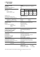
I. SPECIFICATIONS 1. KML-200MAE AC SUPPLY VOLTAGE AMPERAGE MINIMUM CIRCUIT AMPACITY MAXIMUM FUSE SIZE APPROX. ICE PRODUCTION PER 24 HR. lbs./day ( kg./day ) Reference without *marks 115/60/1 10.8 A (5 Min. Freeze AT 104° F / WT 80° F) 20A 20A Ambient Water Temp. (°F) Temp.
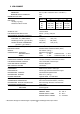
2. KML-200MWE AC SUPPLY VOLTAGE AMPERAGE MINIMUM CIRCUIT AMPACITY MAXIMUM FUSE SIZE APPROX. ICE PRODUCTION PER 24 HR. lbs./day ( kg./day ) Reference without *marks 115/60/1 8.3 A ( 5 Min. Freeze AT 104° F / WT 80° F ) 20A 20A SHAPE OF ICE ICE PRODUCTION PER CYCLE APPROXIMATE STORAGE CAPACITY ELECTRIC & WATER CONSUMPTION ELECTRIC W ( KWH/100 lbs. ) WATER gal./24 HR. ( gal./100 lbs. ) WATER COOLED CONDENSER gal./24 hr. ( gal./100 lbs.
II. GENERAL INFORMATION 1.
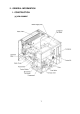
[b] KML-200MWE 8
2. CONTROLLER BOARD [a] SOLID-STATE CONTROL 1) A HOSHIZAKI exclusive solid-state control is employed in KML-200 Series Modular Crescent Cubers. 2) A Printed Circuit Board (hereafter called “Controller Board”) includes a stable and high quality control system. 3) All models are pre-tested and factory-adjusted. [b] CONTROLLER BOARD CAUTION 1. Fragile, handle very carefully. 2. A controller board contains integrated circuits, which are susceptible to failure due to static discharge.
(2) Defrost Timer The defrost cycle starts when the Float Switch opens and completes the freeze cycle. But the Defrost Timer does not start counting until the Thermistor senses 48°F at the Evaporator outlet. The period from the end of the freeze cycle up to the point of the Thermistor's sensing varies depending on the ambient and water temperatures. (3) High Temperature Safety - 127 ± 7°F The temperature of the suction line in the refrigerant circuit is limited by the High Temperature Safety.
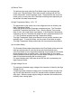
Connector K1 Pin #1 thru #10 #1, 9 #2 #3 #4 #5 #6 #7, 10 #8 Magnetic Contactor Hot Gas Valve Line Valve Pump Motor (icemaking) Pump Motor (drain) Water Valve Power (line, Bin Control) Open Dip Switch Defrost Timer, Drain Timer & Drain Counter Connector K5 Float Switch Connector K4 Open (not connected) Connector K3 Defrost Control (Thermistor) (Alpine “C”/Alpine Board) 11
[c] SEQUENCE 1st Cycle 1. Unit energized and Control Switch to “ICE” position. Water supply cycle starts. 3. Thermistor reads 48° F. Defrost Timer (adjustable from 1 to 3 minutes) starts counting. 2. After 1 minute, Defrost cycle starts. IMPORTANT Water Valve opening is limited to 6 minutes. 4. Defrost Timer stops counting. Defrost cycle is completed and freeze cycle starts. 5. After the first 5 minutes in freeze cycle. Ready to complete freeze cycle when Float Switch circuit opens.
2nd Cycle and after with pump drain IMPORTANT Freeze cycle time is limited to 60 minutes even if Float Switch does not open. 2. Drain Timer stops counting. Pump drain is completed 1. Float Switch opens and signals to complete freeze cycle. 10/20 second Drain Timer starts counting. 3. Thermistor reads 48° F. Defrost Timer (adjustable from 1 to 3 minutes) starts counting. IMPORTANT Water Valve opening is limited to 6 minutes. , & LINE VALVE 5. After the first 5 minutes in freeze cycle.
2nd Cycle and after with no pump drain IMPORTANT Freeze cycle time is limited to 60 minutes even if Float Switch does not open. 2. Thermistor reads 48° F. Defrost Timer (adjustable from 1 to 3 minutes) starts counting. 1. Float Switch opens and signals to complete freeze cycle. IMPORTANT Water Valve opening is limited to 6 minutes. 3. Defrost Timer stops counting. Defrost cycle is completed and freeze cycle starts. 4. After the first 5 minutes in freeze cycle.
[d] CONTROLS AND ADJUSTMENTS (Alpine/Alpine “C” Board) The Dip Switch is factory-adjusted to the following positions: DIP SWITCH NO. KML-200MAE, KML-200MWE 1 2 3 4 5 6 7 8 OFF OFF OFF ON OFF OFF ON ON ON ON ON ON OFF OFF OFF OFF Switch Nos. 1 and 2: Used for adjustment of the Defrost Timer. The Defrost Timer starts counting when the Thermistor reads a certain temperature at the Evaporator outlet. Switch Nos. 3 and 4: Used for adjustment of the Drain Timer.
1) Defrost Control A thermistor (Semiconductor) is used for a defrost control sensor. The resistance varies depending on the Suction Line temperatures. The Thermistor detects the temperature of the Evaporator outlet to start the Defrost Timer. No adjustment is required. If necessary, check for resistance between Thermistor leads, and visually check the Thermistor mounting, located on the Suction Line next to the Evaporator outlet. Temperature (°F) 0 10 32 50 70 90 Resistance (kW) 14.401 10.613 6.000 3.
3) Drain Timer The Drain Timer is factory-adjusted, and no adjustment is required. SETTING Dip Switch Dip Switch No. 3 No. 4 OFF ON OFF ON TIME OFF OFF ON ON T1 T2 10 seconds 10 seconds 10 seconds 20 seconds 150 seconds 180 seconds 120 seconds 180 seconds T1: Time to drain the Water Tank T2: Time to restrain defrost completion 4) Drain Counter CAUTION Do not adjust the Drain Counter, or the Evaporator may freeze up.
5) Bin Control CAUTION When the ambient temperature is below 45°F, the Bin Control Thermostat operates to stop the icemaker even if the Ice Storage Bin is empty. When the Thermostat is set in the prohibited range, the icemaker operates continuously even if the Ice Storage Bin is filled with ice. Setting in the prohibited range might cause severe damage to the icemaker resulting in failure. No adjustment is required under normal use, as the Bin Control is factory-adjusted.
The unit should start the freeze cycle after 1 minute ± 5 seconds from the resistor connection. 3) Check the Controller Board by using test program of the Controller Board. (i) Disconnect the Connector K1 from the Controller Board. Set the Dip Switch No. 7 and 8 on the Controller Board to the “ON” position, and energize the unit. (ii) The current flows to each Relay (from X1 to X4) one after another every time the float is raised and the contacts close.
3. SWITCHES Two control switches are used to control operation in the KML Series Modular Crescent Cubers. These switches are referred to as the “Control Switch” and the “Service Switch.” [a] CONTROL SWITCH The Control Switch is located on the lower left section of the control box when facing the front of the machine. This switch is used to place the machine into one of three modes: “Power Off” (Center position), “Ice Making” (Right position), and “Service” (Left position).
III. TECHNICAL INFORMATION 1.
[b] KML-200MWE 22
Note: KML-200MAE Pressure Switch 2. WIRING DIAGRAMS Cut-out 384 ± 21.3 PSIG Cut-in 284.5 ± 21.3 PSIG [a] KML-200MAE, KML-200MWE KML-200MWE Pressure Switch Cut-out 355.6 ± 21.3 PSIG Cut-in 256 ± 21.
3. TIMING CHART When Control Sw. is turned OFF, Pressure Sw. is OFF, or Thermistor Temp. exceeds t1. From Defrost Cycle To Defrost Cycle If Float Sw. is OFF Hi Temp Mid Temp Lo Temp Too Lo Temp Normal Too Hi Temp Lo Water Time Up (60 sec) Control Sw. in ICE Bin Thermostat ON Max. 60 min Pressure Sw. ON Min. 5 min Overheat Protect Reset * Min. 2 min * Max. 6 min Max. 6 min Max.
To Stand-by Cycle (When Control Sw. is turned OFF, Pressure Sw. is OFF, or Thermistor Temp. exceeds t1.) To Freeze Cycle From Freeze Cycle Control Sw. in WASH *1 *2 Min. 3 min Max. 6 min *2 Max. 6 min Max. 20 min *3 (KM-1200MAE/SAE) *4 (KM-1200MRE/SRE, KM-2000SRE3) *1 The Pump Motor waits for 2 seconds before starting a drain cycle. See “II. 2. [d] CONTROLS AND ADJUSTMENTS.” *2 The icemaker does not complete a defrost cycle in the first 2 or 3 minutes. See “II. 2.
4. PERFORMANCE DATA [a] KML-200MAE APPROXIMATE ICE PRODUCTION PER 24 HR. lbs./day (kg./day) APPROXIMATE ELECTRIC CONSUMPTION watts APPROXIMATE WATER CONSUMPTION PER 24 HR. gal./day (m3/day) FREEZING CYCLE TIME min. HARVEST CYCLE TIME min. HEAD PRESSURE PSIG SUCTION PRESSURE PSIG (kg/cm2G) TOTAL HEAT OF REJECTION AMBIENT TEMP. ( °F/°C ) 50/10 70/21 80/27 90/32 100/38 *250 (113) 241 (109) 230 (104) 218 ( 99) 70/21 80/27 90/32 100/38 *770 774 776 787 70/21 80/27 90/32 100/38 *81 ( 0.31 ) 75 ( 0.
[b] KML-200MWE APPROXIMATE ICE PRODUCTION PER 24 HR. AMBIENT TEMP. ( °F/°C ) lbs./day (kg./day) APPROXIMATE ELECTRIC CONSUMPTION watts APPROXIMATE WATER CONSUMPTION PER 24 HR. gal./day (m3/day) FREEZING CYCLE TIME min. HARVEST CYCLE TIME min. HEAD PRESSURE PSIG SUCTION PRESSURE PSIG 70/21 80/27 90/32 100/38 50/10 *238 ( 108 ) 232 ( 105 ) 223 ( 101 ) 215 ( 98 ) 70/21 80/27 90/32 100/38 *700 707 709 709 70/21 80/27 90/32 100/38 *226 ( 0.86 ) 266 ( 1.00 ) 279 ( 1.06 ) 295 ( 1.12 ) WATER TEMP.
IV. SERVICE DIAGNOSIS 1. NO ICE PRODUCTION PROBLEM [1] The icemaker will not start POSSIBLE CAUSE a) Power Supply 1. “OFF” position. 2. Loose connections. 3. Bad contacts. 4. Voltage too high. b) Fuse (Inside Fused Disconnect, if any) c) Control Switch d) Bin Control Thermostat e) High Pressure Control f) Transformer g) Wiring to Controller Board h) Thermistor i) Hot Gas Solenoid Valve j) Water Supply Line k) Water Solenoid 1. Blown out. 1. “OFF” position. 2. Bad contacts. 1.
PROBLEM [2] Water continues to be supplied, and the icemaker will not start. [3] Compressor POSSIBLE CAUSE REMEDY l) Controller Board 1. Defective a) Float switch 1. Connector disconnected. 2. Leads opened or defective switch. 3. Float does not move freely. 3. Clean or replace. 1. Defective. 1. Replace. b) Controller Board a) Control Switch b) High Pressure Controller c) Water Regulator d) Overload Protector e) Starter 1. “SERVICE” position. 2. Bad contacts. 1. Dirty Air Filter or Condenser. 2.
PROBLEM [4] Water continues to be supplied in freeze cycle. [5] No water comes from Spray Tubes. Water Pump will not start, or freeze cycle time is too short. POSSIBLE CAUSE a) Water Solenoid Valve b) Controller Board a) Water Supply Line b) Water Solenoid Valve c) Water System d) Pump Motor e) Controller Board [6] Fan Motor will a) Fan Motor not start, or is not operating. b) Controller Board [7] All components a) Refrigerant run but no ice is produced.
2. EVAPORATOR IS FROZEN UP PROBLEM [1] Freeze cycle time is too long. POSSIBLE CAUSE a) Float Switch b) Water Solenoid Valve c) Controller Board [2] All ice formed a) Evaporator on Evaporator b) Water Supply Line does not fall into bin in c) Water Solenoid harvest cycle. Valve d) Ambient and/or water temperature e) Thermistor f) Controller Board 1. Leads short-circuit or 1. Check and replace. defective switch. 2. Float does not move freely. 2. Clean or replace. 1. Diaphragm does not close. 1.
4. ABNORMAL ICE PROBLEM [1] Small Cube POSSIBLE CAUSE REMEDY a) Ice Cube Guide 1. Out of position. 1. Place in position. Circulated water falls into bin. b) See chart 1 - [5], and check water supply line, Water Solenoid Valve, water system, Pump Motor or Controller Board. c) Drain Valve 1. Dirty. 1. Clean. [2] Cloudy or a) See chart 2 - [1] and - [3], and check Float Switch, Water Solenoid Valve, irregular cube Controller Board, Spray Tubes, water system, refrigerant charge or Expansion Valve.
V. REMOVAL AND REPLACEMENT OF COMPONENTS 1. SERVICE FOR REFRIGERANT LINES [a] REFRIGERANT RECOVERY The icemaker unit is provided with two Refrigerant Access Valves on the low-side and high-side lines. Recover the refrigerant from the Access Valves and store it in an approved container. Do not discharge the refrigerant into the atmosphere. [b] EVACUATION AND RECHARGE 1) Attach Charging Hoses, a Service Manifold and a Vacuum Pump to the system.
2. BRAZING WARNING 1. Refrigerant R22 itself is not flammable, explosive or poisonous. However, when exposed to an open flame, R22 creates Phosgene gas, hazardous in large amounts. 2. Always recover the refrigerant and store it in an approved container. Do not discharge the refrigerant into the atmosphere. 3. Do not use silver alloy or copper alloy containing Arsenic. Note: All brazing-connections in the Evaporator Case are clear-paint coated.
7) Slide and remove the Compressor. Unpack the new Compressor package. Install the new Compressor. 8) Attach the Rubber Grommets of the prior Compressor. 9) Sandpaper the Suction, Discharge and Process Pipes. 10) Place the Compressor in position, and secure it using the Bolts and Washers. 11) Remove plugs from the Suction, Discharge and Process Pipes. 12) Braze the Process, Suction and Discharge lines (Do not change this order), while purging with nitrogen gas flowing at the pressure 3 - 4 PSIG.
4. REMOVAL AND REPLACEMENT OF DRIER IMPORTANT Always install a new Drier every time the sealed refrigeration system is opened. Do not replace the Drier until after all other repair or replacement has been made. 1) Turn off the power supply. 2) Remove the panels. 3) Recover the refrigerant and store it in an approved container. 4) Remove the Drier. 5) Install the new Drier, with the arrow on the Drier, in the direction of the refrigerant flow.
4) Remove the insulation and the Expansion Valve Bulb on the suction line. 5) Remove the Expansion Valve Cover, and disconnect the Expansion Valve using brazing equipment. 6) Braze the new Expansion Valve, with nitrogen gas flowing at the pressure of 3 - 4 PSIG. WARNING Always protect the valve body by using a damp cloth to prevent the valve from overheating. Do not braze with the valve body exceeding 250°F. 7) Install the new Drier. 8) Check for leaks using nitrogen gas (140 PSIG) and soap bubbles.
IMPORTANT Always install a new Drier every time the sealed refrigeration system is opened. Do not replace the Drier until after all other repair or replacement has been made. 1) Turn off the power supply. 2) Remove the panels. 3) Recover the refrigerant and store it in an approved container. 4) Remove the screw and the Solenoid. 5) Disconnect the Hot Gas Valve or Line Valve. 6) Install the new valve. WARNING Always protect the valve body by using a damp cloth to prevent the valve from overheating.
7. REMOVAL AND REPLACEMENT OF EVAPORATOR IMPORTANT Always install a new Drier every time the sealed refrigeration system is opened. Do not replace the Drier until after all other repairs or replacement have been made. 1) Turn off the power supply. 2) Remove the panels and the Top Insulation over the Evaporator. 3) Recover the refrigerant and store it in an approved container.
8. REMOVAL AND REPLACEMENT OF WATER REGULATING VALVE WATER-COOLED MODEL ONLY IMPORTANT Always install a new Drier every time the sealed refrigeration system is opened. Do not replace the Drier until after all other repair or replacement has been made. 1) Turn off the power supply. 2) Close the Water Supply Line Shut-off Valve. 3) Remove the panels. 4) Recover the refrigerant and store it in an approved container. 5) Disconnect the Capillary Tube at the Condenser outlet using brazing equipment.
9. ADJUSTMENT OF WATER REGULATING VALVE - WATER-COOLED MODEL ONLY The Water Regulating Valve (also called “WATER REGULATOR”) is factory-adjusted. No adjustment is required under normal use. Adjust the Water Regulator, if necessary, using the following procedures. 1) Attach a pressure gauge to the high-side line of the system. Or prepare a thermometer to check for the condenser drain temperature.
10. REMOVAL AND REPLACEMENT OF THERMISTOR CAUTION 1. Fragile, handle very carefully. 2. Always use a recommended sealant (High Thermal Conductive Type), Model KE4560RTV manufactured by SHINETSU SILICONE, Part Code 60Y000-11, or Part Code 4A0683-01 or equivalent. 3. Always use a recommended foam insulation (Non-absorbent Type) or equivalent. 4. Do not shorten or cut the Thermistor leads when installing it. 1) Turn off the power supply. Thermistor Lead 2) Remove the panels.
10) Secure the insulation using the Plastic Cable Ties. 11) Connect the Thermistor leads through the bushing of the Control Box to the K3 Connector on the Controller Board. Note: Do not cut the leads of the Thermistor while installing it. 12) Replace the Control Box Cover and the panels in their correct positions. 13) Turn on the power supply. 11. REMOVAL AND REPLACEMENT OF FAN MOTOR Note: When replacing a Fan Motor with defective winding, it is recommended that a new capacitor be installed.
12. REMOVAL AND REPLACEMENT OF WATER VALVE 1) Turn off the power supply. 2) Close the Water Supply Line Shut-off Valve. 3) Remove the Front Panel. 4) Remove the Valve Outlet Tubing by releasing the Clamp. 5) Remove the Bracket from the unit. 6) Remove the Fitting Nut and Water Valve. 7) Disconnect the Terminals from the Water Valve. 8) Install the new Water Valve, and replace the removed parts in the reverse order of which they were removed. 9) Open the Water Supply Line Shut-off Valve.
14. REMOVAL AND REPLACEMENT OF SPRAY TUBE 1) Turn off the power supply. 2) Remove the Front Panel and the Insulation Panel. 3) Release the Clamps, and disconnect the Rubber Hoses. 4) Remove the Spray Tubes by squeezing the side tabs. 5) Install the new Spray Tubes, and replace the removed parts in the reverse order of which they were removed. 6) Replace the panels in their correct positions. 7) Turn on the power supply.
VI. CLEANING AND MAINTENANCE INSTRUCTIONS 1. PREPARING THE ICEMAKER FOR LONG STORAGE CAUTION When shutting off the icemaker for an extended time, drain out all water from the water line and remove the ice from the Storage Bin. The Storage Bin should be cleaned and dried. Drain the icemaker to prevent damage to the water supply line at sub-freezing temperatures, using air or carbon dioxide. Shut off the icemaker until the proper ambient temperature is resumed.
[2] Remove the water from the potable water supply line: 1) Turn off the power supply and remove the Front Panel. 2) Move the Control Switch, on the Control Box, to the “OFF” position. 3) Wait 3 minutes. 4) Close the Potable Water Supply Line Shut-off Valve and open the Potable Water Supply Line Drain Valve. See Fig. 4. 5) Allow the line to drain by gravity. 6) Attach compressed air or carbon dioxide supply to the Potable Water Line Drain Valve. 7) Move the Control Switch to the “ICE” position.
2. CLEANING WARNING 1. HOSHIZAKI recommends cleaning this unit at least once a year. More frequent cleaning, however, may be required in some existing water conditions. 2. To prevent injury to individuals and damage to the icemaker, do not use ammonia type cleaners. 3. Always wear liquid-proof gloves for safe handling of the cleaning and sanitizing solution. This will prevent irritation in case the solution contacts with skin. 1) Dilute approximately 10.5 fl. oz.
11) Replace the Insulation Panel and the Front Panel in their correct positions. 12) Turn on the power supply and start the washing process. 13) Turn off the power supply after 30 minutes. 14) Remove the Front Panel. 15) Move the Service Switch to the “DRAIN” position. 16) Replace the Front Panel and turn on the power supply for 2 minutes. 17) Turn off the power supply and remove the Front Panel. 18) Move the Control Switch to the “ICE” position. 19) Replace the Front Panel in its correct position.
3. SANITIZING PROCEDURE - Following Cleaning Procedure 1) Dilute IMS-II Sanitizer or a 5.25% Sodium Hypochlorite solution with water (Add 1.0 fl. oz. to 2 gal. of water). Note: IMS-II Sanitizer, Part #SA0004, is available through your Hoshizaki Dealer. 2) Remove the Insulation Panel. 3) Pour the sanitizing solution into the Water Tank. 4) Move the Service Switch to the “WASH” position. 5) Replace the Insulation Panel and the Front Panel in their correct position.
4. MAINTENANCE IMPORTANT This icemaker must be maintained individually, referring to the instruction manual and labels provided with the icemaker. 1) Stainless Steel Exterior To prevent corrosion, wipe the exterior occasionally with a clean and soft cloth. Use a damp cloth containing a neutral cleaner to wipe off oil or dirt build up. 2) Storage Bin and Scoop • Wash your hands before removing ice. Use the plastic scoop provided (Accessory). • The Storage Bin is for ice use only.