NO: ISSUED: 73081 OCT. 9, 1998 REVISED: DEC.
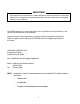
IMPORTANT Only qualified service technicians should attempt to service or maintain this icemaker. No service or maintenance should be undertaken until the technician has thoroughly read this Service Manual. HOSHIZAKI provides this manual primarily to assist qualified service technicians in the service and maintenance of the icemaker.
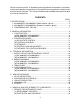
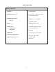
Please review this manual. It should be read carefully before the icemaker is serviced or maintenance operations are performed. Only qualified service technicians should service and maintain the icemaker. This manual should be made available to the technician prior to service or maintenance. CONTENTS PAGE I. SPECIFICATIONS .................................................................................................... 5 1. KM-2000SWF3, KM-2000SWH3 (Water-cooled, 3 phase) ...............................
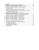
2. 3. 4. 5. 6. 7. 8. 9. 10. 11. 12. 13. 14. 15. BRAZING ............................................................................................................. 37 REMOVAL AND REPLACEMENT OF COMPRESSOR...................................... 38 REMOVAL AND REPLACEMENT OF DRIER .................................................... 39 REMOVAL AND REPLACEMENT OF EXPANSION VALVE .............................. 40 REMOVAL AND REPLACEMENT OF HOT GAS VALVE ....................................... AND LINE VALVE .
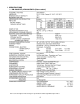
I. SPECIFICATIONS 1. KM-2000SWF3, KM-2000SWH3 (Water-cooled) We reserve the right to make changes in specifications and design without prior notice.
2. KM-2000SRF3, KM-2000SRH3 (Remote air-cooled) We reserve the right to make changes in specifications and design without prior notice.
3.
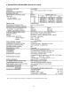
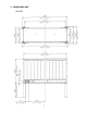
SPECIFICATIONS MODEL: URC-20F EXTERIOR Galvanized Steel DIMENSIONS (W x D x H) 46 - 3/8" x 15 - 11/16" x 25 - 15/16" (1178 x 398 x 659 mm) REFRIGERANT CHARGE R404A 7 lbs.11 oz. (3500 g) URC-20F Net 104 lbs. (47 kg) Shipping 150 lbs. (52 kg) WEIGHT One Shot Couplings (Aeroquip) Permanent Connection CONNECTIONS REFRIGERANT ELECTRICAL Air-cooled CONDENSER Condensing Pressure Regulator HEAD PRESSURE CONTROL Min. -20°F - Max.
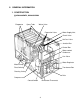
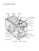
II. GENERAL INFORMATION 1.
[b] KM-2000SRF3, KM-2000SRH3 Evaporator Spray Tube Water Valve Expansion Valve Water Supply Inlet Check Valve Hot Gas Valve Junction Box Control Box Receiver Tank Water Pump Line Valve Float Switch Transformer Box Cleaning Valve Drier Compressor Control Switch Bin Control Thermostat 10
2. CONTROLLER BOARD [a] SOLID-STATE CONTROL 1) A HOSHIZAKI exclusive solid-state control is employed in KM-2000SWF3, KM-2000SRF3, KM-2000SWH3, and KM-2000SRH3 Stackable Crescent Cubers. 2) A Printed Circuit Board (hereafter called “Controller Board”) includes a stable and high quality control system. 3) All models are pretested and factory-adjusted. [b] CONTROLLER BOARD CAUTION 1. Fragile, handle very carefully. 2.
2) Defrost Timer The defrost cycle starts when the Float Switch opens and completes the freeze cycle. But the Defrost Timer does not start counting until the Thermistor senses 48°F at the Evaporator outlet. The period from the end of the freeze cycle up to the point of the Thermistor's sensing varies depending on the ambient and water temperatures. 3) High Temperature Safety - 127 ± 7°F The temperature of the suction line in the refrigerant circuit is limited by the High Temperature Safety.
problem occurs. At startup a 5 second delay occurs while the board conducts an internal timer check. A short beep occurs when the power switch is turned ON or OFF. The green LED’s 1-4 represent the corresponding relays and energize and sequence 5 seconds from initial startup as follows: Sequence Step 1 Minute Fill Cycle Harvest Cycle Freeze Cycle Reverse Pump Out LED’s on Length: LED4 LED1, 4, & 2 LED1 LED1, 3, & 2 Min. Max. 2 min. 5 min. 10 sec. 20 min. 60 min. 20 sec. Avg. 60 sec. 3-5 min.
to the K1 connector. If there is a white wire, place the switch in the C position. If this switch is placed in the wrong position either the compressor contactor will remain energized with the control switch OFF or the unit will not start. The dip switches should be adjusted per the adjustment chart published in the Tech Specs book. 7 & 8 must remain in the OFF position.
(Control Products HOS-001A Board) 15
[c] SEQUENCE 1st Cycle [KM-2000SWF3, KM-2000SRF3, KM-2000SWH3 and KM-2000SRH3] 3. Thermistor reads 48°F. Defrost Timer starts counting. 1. Unit energized and Control Switch to “ICE” position. Water supply cycle starts. 2. After 1 minute. Defrost cycle starts. IMPORTANT Water Valve opening is limited to 6 minutes. 5. After the first 5 minutes in freeze cycle. Ready to complete freeze cycle when Float Switch circuit opens. 4. Defrost Timer stops counting.
2nd Cycle and after with pump drain [KM-2000SWF3, KM-2000SRF3, KM-2000SWH3 and KM-2000SRH3] IMPORTANT Freeze cycle time is limited to 60 minutes even if Float Switch does not open. 2. Drain timer stops counting. Pump drain is completed 1. Float Switch opens and signals to complete freeze cycle. Drain timer starts counting. 3. Thermistor reads 48° F. Defrost Timer starts counting. IMPORTANT Water Valve opening is limited to 6 minutes. & 5. After the first 5 minutes in freeze cycle.
2nd Cycle and after with no pump drain [KM-2000SWF3, KM-2000SRF3, KM-2000SWH3 and KM-2000SRH3] IMPORTANT Freeze cycle time is limited to 60 minutes even if Float Switch does not open. 2. Thermistor reads 48° F. Defrost Timer starts counting. 1. Float Switch opens and signals to complete freeze cycle. IMPORTANT Water Valve opening is limited to 6 minutes. 3. Defrost Timer stops counting. Defrost cycle is completed and freeze cycle starts. 4. After the first 5 minutes in freeze cycle.
[d] CONTROLS AND ADJUSTMENTS The Dip Switch is factory-adjusted to the following positions: DIP SWITCH NO. KM-2000S_F3, KM-2000S_H3 1 2 3 OFF OFF ON 4 5 6 7 8 ON ON ON OFF OFF 9 10 OFF OFF Switch Nos. 1 and 2: Used for adjustment of the Defrost Timer. The Defrost Timer starts counting when the Thermistor reads a certain temperature at the Evaporator outlet. Switch Nos. 3 and 4: Used for adjustment of the Drain Timer.
1) Defrost Control A thermistor (Semiconductor) is used for a defrost control sensor. The resistance varies depending on the Suction Line temperatures. The Thermistor detects the temperature of the Evaporator outlet to start the Defrost Timer. No adjustment is required. If necessary, check for resistance between Thermistor leads, and visually check the Thermistor mounting, located on the Suction Line next to the Evaporator outlet. Temperature (°F) 0 10 32 50 70 90 Resistance (kΩ) 14.401 10.613 6.000 3.
3) Drain Timer The Drain Timer is factory-adjusted, and no adjustment is required. SETTING Dip Switch Dip Switch No. 3 No. 4 OFF ON OFF ON TIME T1 OFF OFF ON ON T2 10 seconds 10 seconds 10 seconds 20 seconds 150 180 120 180 seconds seconds seconds seconds T1: Time to drain the Water Tank T2: Time to restrain defrost completion 4) Drain Counter CAUTION Do not adjust the Drain Counter, or the Evaporator may freeze up.
5) Freeze Timer CAUTION Adjust to proper specification, or the unit may not operate correctly. Two new dip switches numbered 9 and 10 have been added to the improved “E” board to better prevent possible freeze ups. These settings come factory set to the default setting of 60 min. (OFF, OFF). Check the adjustment chart published in the Tech Specs for proper settings. If the old board does not have these two dip switches, (only 8 instead of 10), leave setting as OFF, OFF. SETTING Dip Switch Dip Switch No.
After the 1 minute ± 5 second water supply cycle and the 2 minute ± 10 second defrost cycle, the unit should start the freeze cycle. (ii) After the above step (i), disconnect the Float Switch leads from the Controller Board within the first 5 minutes of the freeze cycle. The unit should go into the defrost cycle after the first 5 minutes ± 20 seconds of the freeze cycle. (iii) Reconnect the Float Switch Connector to the Controller Board.
III. TECHNICAL INFORMATION 1.
[b] KM-2000SRF3, KM-2000SRH3 25
2. WIRING DIAGRAMS [a] KM-2000SWF3 KM-2000SWH3 [b] KM-2000SRF3 KM-2000SRH3 KM-2000SWF3, KM-2000SWH3 KM-2000SRF3, KM-2000SRH3 Pressure Switch Pressure Switch Cut-out 384 +21.3 0 PSIG Cut-out 412 +21.3 0 PSIG Cut-in 284 ± 21.3 PSIG Cut-in 327 ± 21.
3. TIMING CHART *1 The icemaker does not complete a defrost cycle in the first 2 or 3 minutes. See “II. 2. [d] CONTROLS AND ADJUSTMENTS.
*1 The Pump Motor waits for 2 seconds before starting a drain cycle. See “II. 2. [d] CONTROLS AND ADJUSTMENTS.” *2 The icemaker does not complete a defrost cycle in the first 2 or 3 minutes. See “II. 2. [d] CONTROLS AND ADJUSTMENTS.
4. PERFORMANCE DATA [a] KM-2000SWF3, KM-2000SWH3 Note: Pressure data is recorded first 5 minutes in freezing cycle. The data not in bold should be used for reference. We reserve the right to make changes in specifications and design without prior notice.
[b] KM-2000SRF3, KM-2000SRH3 Note: Pressure data is recorded first 5 minutes in freezing cycle. The data not in bold should be used for reference. We reserve the right to make changes in specifications and design without prior notice.
IV. SERVICE DIAGNOSIS 1. NO ICE PRODUCTION PROBLEM [1] The icemaker will not start POSSIBLE CAUSE a) Power Supply 1. “OFF” position. 2. Loose connections. 3. Bad contacts. 4. Voltage too high. b) Fuse (Inside Fused Disconnect, if any) c) Control Switch d) Bin Control Thermostat e) High Pressure Control f) Transformer g) Wiring to Controller Board h) Thermistor i) Hot Gas Solenoid Valve j) Water Supply Line k) Water Solenoid 1. Blown out. 1. “OFF” position. 2. Bad contacts. 1.
PROBLEM POSSIBLE CAUSE l) Controller Board m) Interlock Switch (Cleaning Valve) [2] Water continues to be supplied, and the icemaker will not start. [3] Compressor will not start or stops operating a) Float switch b) Controller Board a) Wash Switch b) High Pressure Controller c) Water Regulator d) Overload Protector e) Starter f) Start Capacitor or Run Capacitor g) Magnetic Contactor [4] Water continues to be supplied in freeze cycle. 1. Defective. 1. “OFF” position. 2. Bad contacts. 1.
PROBLEM POSSIBLE CAUSE [5] No water a) Water Supply Line comes from Spray Tubes. Water Pump b) Water Solenoid will not start, or Valve freeze cycle time is too c) Water System short. d) Pump Motor e) Controller Board [6] Fan Motor will a) Fan Motor not start, or is not operating. b) Controller Board [7] All components a) Refrigerant run but no ice is produced. b) Compressor c) Hot Gas Solenoid Valve d) Line Valve e) Water Solenoid Valve f) Water Supply Line [Water-cooled model only] 1.
2. EVAPORATOR IS FROZEN UP PROBLEM [1] Freeze cycle time is too long. POSSIBLE CAUSE a) Float Switch a) Evaporator b) Water Supply Line 1. Scaled up. 1. Water pressure too low. c) Water Filter System d) Water Solenoid Valve e) Ambient and/or water temperature f) Line Valve 1. Dirty/Restricted. 1. Dirty mesh filter or orifice. 1. Too cool. 1. Increase temperature. 1. Continues to open in harvest cycle. 1. Out of position or loose attachment. 1. Check operation in harvest cycle and replace. 1. See “V.
3. LOW ICE PRODUCTION PROBLEM [1] Freeze cycle time is long. [2] Harvest cycle time is long POSSIBLE CAUSE REMEDY a) See chart 1 - [3], and check dirty Air Filter or Condenser, ambient or water temperature, water pressure, Water Regulator or refrigerant charge. b) See chart 2 - [1], and check Float Switch, Water Solenoid Valve or Controller Board.
V. REMOVAL AND REPLACEMENT OF COMPONENTS IMPORTANT Ensure all components, fasteners and thumbscrews are securely in place after the equipment is serviced. IMPORTANT 1. The Polyol Ester (POE) oils used in R-404A units can absorb moisture quickly. Therefore it is important to prevent moisture from entering the system when replacing or servicing parts. 2. Always install a new filter drier every time the sealed refrigeration system is opened. 3.
5) Disconnect the Vacuum Pump, and attach a Refrigerant Service Cylinder to the Highside line. Remember to loosen the connection, and purge the air from the Hose. For water-cooled models, see the Nameplate for the required refrigerant charge. For remote air-cooled models, see the Charge Label in the machine compartment. Hoshizaki recommends only virgin refrigerant or reclaimed refrigerant which meets ARI Standard No. 700-88 be used. 6) A liquid charge is recommended for charging an R-404A system.
3. REMOVAL AND REPLACEMENT OF COMPRESSOR IMPORTANT Always install a new Drier every time the sealed refrigeration system is opened. Do not replace the Drier until after all other repair or replacement has been made. Note: When replacing a Compressor with a defective winding, be sure to install the new Start Capacitor and Start Relay supplied with the replacement Compressor.
15) Evacuate the system, and charge it with refrigerant. See the Nameplate for the required refrigerant charge. 16) Connect the Terminals, and replace the Terminal Cover in its correct position. 17) Replace the panels in their correct positions. 18) Turn on the power supply. 4. REMOVAL AND REPLACEMENT OF DRIER IMPORTANT Always install a new Drier every time the sealed refrigeration system is opened. Do not replace the Drier until after all other repair or replacement has been made.
5. REMOVAL AND REPLACEMENT OF EXPANSION VALVE IMPORTANT Sometimes moisture in the refrigerant circuit exceeds the Drier capacity and freezes up at the Expansion Valve. Always install a new Drier every time the sealed refrigeration system is opened. Do not replace the Drier until after all other repair or replacement has been made. 1) Turn off the power supply. 2) Remove the panels. 3) Recover the refrigerant and store it in an approved container.
6. REMOVAL AND REPLACEMENT OF HOT GAS VALVE AND LINE VALVE CAUTION Always use a copper tube of the same diameter and length when replacing the hot gas lines; otherwise the performance may be reduced. IMPORTANT Always install a new Drier every time the sealed refrigeration system is opened. Do not replace the Drier until after all other repair or replacement has been made. 1) Turn off the power supply. 2) Remove the panels. 3) Recover the refrigerant and store it in an approved container.
11) Connect the new Solenoid leads. 12) Attach the Solenoid to the valve body, and secure it with a screw. 13) Replace the panels in their correct positions. 14) Turn on the power supply. 7. REMOVAL AND REPLACEMENT OF EVAPORATOR IMPORTANT Always install a new Drier every time the sealed refrigeration system is opened. Do not replace the Drier until after all other repairs or replacement have been made. 1) Turn off the power supply. 2) Remove the panels and the Top Insulation over the Evaporator.
8. REMOVAL AND REPLACEMENT OF WATER REGULATING VALVE WATER-COOLED MODEL ONLY IMPORTANT Always install a new Drier every time the sealed refrigeration system is opened. Do not replace the Drier until after all other repair or replacement has been made. 1) Turn off the power supply. 2) Close the Water Supply Line Shut-off Valve. 3) Remove the panels. 4) Recover the refrigerant and store it in an approved container. 5) Disconnect the Capillary Tube at the Condenser outlet using brazing equipment.
9. ADJUSTMENT OF WATER REGULATING VALVE - WATER-COOLED MODEL ONLY The Water Regulating Valve (also called “WATER REGULATOR”) is factory-adjusted. No adjustment is required under normal use. Adjust the Water Regulator, if necessary, using the following procedures. 1) Attach a pressure gauge to the high-side line of the system. Or prepare a thermometer to check for the condenser drain temperature.
10. REMOVAL AND REPLACEMENT OF CONDENSING PRESSURE REGULATOR (C.P.R.) - REMOTE AIR-COOLED MODEL ONLY IMPORTANT Always install a new Drier every time the sealed refrigeration system is opened. Do not replace the Drier until after all other repair or replacement has been made. 1) Turn off the power supply. 2) Remove the panels from the remote condenser unit. 3) Recover the refrigerant and store it in an approved container. 4) Before heating, break off the stub on the dome to release the dome charge.
11. REMOVAL AND REPLACEMENT OF THERMISTOR CAUTION 1. Fragile, handle very carefully. 2. Always use a recommended sealant (High Thermal Conductive Type), Model KE4560RTV manufactured by SHINETSU SILICONE, Part Code 60Y000-11, or Part Code 4A0683-01 equivalent. 3. Always use a recommended foam insulation (Non-absorbent Type) or equivalent. 1) Turn off the power supply. 2) Remove the panels. Thermistor Lead Cable Tie Foam Insulation Thermistor Holder 3) Remove the Control Box Cover.
12. REMOVAL AND REPLACEMENT OF FAN MOTOR Note: When replacing a Fan Motor with defective winding, it is recommended that a new capacitor be installed. 1) Turn off the power supply. 2) Remove the panels. 3) Remove the Junction Box Cover from the remote condenser unit (Remote Air-cooled model). 4) Remove the closed end connectors from the Fan Motor leads. 5) Remove the Fan Motor Bracket and Fan Motor. 6) Install the new Fan Motor, and replace the removed parts in the reverse order of which they were removed.
13. REMOVAL AND REPLACEMENT OF WATER VALVE 1) Turn off the power supply. 2) Close the Water Supply Line Shut-off Valve. 3) Remove the Front Panel. 4) Remove the Valve Outlet Tubing by releasing the Clamp. 5) Remove the Bracket from the unit. 6) Remove the Fitting Nut and Water Valve. 7) Disconnect the Terminals from the Water Valve. 8) Install the new Water Valve, and replace the removed parts in the reverse order of which they were removed. 9) Open the Water Supply Line Shut-off Valve.
7) Remove the closed end connectors from the Pump Motor leads. 8) Remove the two screws and the Pump Motor Bracket. 9) Remove the Pump Housing, and check the Impeller. 10) If the Impeller is defective, install a new Impeller. 11) Install the new motor or new parts, and replace the removed parts in the reverse order of which they were removed. 12) Turn on the power supply, and check for leaks. 13) Replace the Front Panel in its correct position. 15.
VI. CLEANING AND MAINTENANCE INSTRUCTIONS 1. PREPARING THE ICEMAKER FOR LONG STORAGE IMPORTANT Ensure all components, fasteners and thumbscrews are securely in place after any maintenance or cleaning is done to the equipment. WARNING When shutting off the icemaker for an extended time, drain out all water from the water tank and remove the ice from the Storage Bin. The Storage Bin should be cleaned and dried.
[2] Remove the water from the potable water supply line: 1) Remove the Front Panel. (Except water-cooled model) 2) Move the Control Switch, on the Control Box, to the “OFF” position. 3) Wait 3 minutes. 4) Close the Potable Water Supply Line Shut-off Valve and open the Potable Water Supply Line Drain Valve. 5) Allow the line to drain by gravity. 6) Attach compressed air or carbon dioxide supply to the Potable Water Line Drain Valve. 7) Move the Control Switch to the “ICE” position.
2. CLEANING PROCEDURE IMPORTANT Ensure all components, fasteners and thumbscrews are securely in place after any maintenance or cleaning is done to the equipment. WARNING 1. HOSHIZAKI recommends cleaning this unit at least once a year. More frequent cleaning, however, may be required in some existing water conditions. 2. To prevent injury to individuals and damage to the icemaker, do not use ammonia type cleaners. 3. Always wear liquid-proof gloves for safe handling of the cleaning and sanitizing solution.
[a] CLEANING PROCEDURE 1) Dilute 38 fl. oz. of the recommended cleaner Hoshizaki “Scale Away” or “LIME-A-WAY” (Economics Laboratory, Inc.) with 7 gal. of water. 2) Remove all ice from the Evaporator and the Storage Bin. Note: To remove cubes on the Evaporator, turn off the power supply and turn it on after 3 minutes. The defrost cycle starts and the cubes will be removed from the Evaporator. 3) Turn off the power supply.
19) Turn on the power supply to fill the Water Tank with water. 20) Turn off the power supply after 3 minutes. 21) Remove the Front Panel, and fully open the Cleaning Valve. 22) Move the Control Switch to the “Wash” position. 23) Replace the Front Panel in its correct position. 24) Turn on the power supply to rinse off the cleaning solution. 25) Turn off the power supply after 5 minutes. 26) Remove the Front Panel and Insulation Panel.
[b] SANITIZING PROCEDURE - Following Cleaning Procedure 1) Dilute a 5.25% Sodium Hypochlorite solution (chlorine bleach) with water (Add 3.5 fl. oz. of sanitizer to 7 gal. of water). 2) Remove the Insulation Panel, if it is in its normal position. 3) Pour the sanitizing solution into the Water Tank. 4) Replace the Insulation Panel and the Front Panel in their correct positions. Note: Make sure that the Control Switch is in the “WASH” position and the Cleaning Valve is in the “Open” position.
3. MAINTENANCE IMPORTANT This icemaker must be maintained individually, referring to the instruction manual and labels provided with the icemaker. 1) Stainless Steel Exterior To prevent corrosion, wipe the exterior occasionally with a clean and soft cloth. Use a damp cloth containing a neutral cleaner to wipe off oil or dirt build up. 2) Storage Bin and Scoop • Wash your hands before removing ice. Use the plastic scoop provided. • The Storage Bin is for ice use only. Do not store anything else in the bin.