
Parts Manual


5
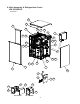
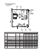
Title: A. Main Assembly & Refrigeration Circuit Model: KM-1601MRH/3
Index
No.
Description
Material or
Model Number Part Number
Required Number
Q-0
to
U-0
U-1
to
A-0
A-1
to
D-1
Main Assembly
1 Front Panel 2A2164-02 1 1 1
2 Gasket L=762 mm 4A0808L02 1 1 1
3 Top Panel 3A1941A01 1 1 1
4 Right Side Panel 2A2165G01 1 1 1
5 Front Insulation 322711G01 1 1 1
6 Top Insulation 322714G01 1 1 1
7 Control Box Cover 3A2386-01 1 1 1
8 Junction Box Cover 433410-01 2 2 2
9 Bin Control Bulb Holder 322815G02 1 1 1
9a Thumbscrew 415949G10 2 2 2
10 Bin Control Bulb Holder 3A3903-01 1 1 1
11 Silicone Hose L=285 mm 7730I3812 1 1 1
12 Run Capacitor KM-1601MRH
35MFD, 370VAC
3A2005-05 1 1 1
13 Start Capacitor KM-1601MRH
145-175MFD,
250V
3A0076-01 1 1 1
14 Start Relay KM-1601MRH 4A1107-09 1 1 1
15 Capacitor Box Cover KM-1601MRH 326125-01 1 1 1
16 Main Transformer KM-1601MRH3 4A0817-01 1 1 1
17 Voltage Tap Switch KM-1601MRH3 4A1477-01 1 1 1
Refrigeration Circuit
18 Compressor
(A-1 and later utilize external
crankcase heater - item 19)
KM-1601MRH 4A2334-02 1 1 -
4A2334-01 1
KM-1601MRH3 4A2330-02 1 1 -
4A2330-01 1
19 Crankcase Heater 4A5397-02 1
20 Receiver 440366-01 1 1 1
20a Hex Head Bolt w/Washer 5×10 7B0130510 3 3 3
21 Evaporator (includes item 22) 104442G03 1 1 1
22 Evaporator Plate S-0428 103317G01 4 4 4
23 Thermostatic Expansion Valve 4A1482-01 2 2 2
24 Thermostatic Expansion Valve
Cover
3A0944-01 2 2 2
25 Thermostatic Expansion Valve
Bulb Holder
3A0107-01 2 2 2
26 Hot Gas Valve Body 4A3978-01 1 1 1
27 Liquid Line Valve Body 4A3276-01 1 1 1
28 Valve Coil 4A3277-01 2 2 2
29 Check Valve 4A1373-01 2 2 2
30 Strainer 441569-02 1 1 1
31 High-Pressure Switch 433441-07 1 -
463180-04 1 1
32 Thermistor 429006-03 1 1 1
33 Thermistor Holder 427430-01 1 1 1
34 Drier 4A2663-01 1 1 1
35 Discharge Line Coupling 434136G01 1 1 1
36 Liquid Line Coupling 433751G01 1 1 1