Hoshizaki Hoshizaki America, Inc. Self-Contained Flaker Model F-300BAF “A Superior Degree of Reliability” SERVICE MANUAL www.hoshizaki.
IMPORTANT Only qualified service technicians should attempt to service or maintain this unit. No such service or maintenance should be undertaken until the technician has thoroughly read this Service Manual. HOSHIZAKI provides this manual primarily to assist qualified service technicians in the service and maintenance of the unit.
Please review this manual. It should be read carefully before the unit is serviced or maintenance operations are performed. Only qualified service technicians should service and maintain the unit. This manual should be made available to the technician prior to service or maintenance. CONTENTS I. Specifications....................................................................................................................... 5 A. Icemaker...................................................................
V. Removal and Replacement of Components..................................................................... 33 A. Service for Refrigerant Lines........................................................................................ 33 1. Refrigerant Recovery ............................................................................................. 33 2. Evacuation and Recharge [R-404A]....................................................................... 33 B. Brazing..................................
I. Specifications A. Icemaker 1. F-300BAF AC SUPPLY VOLTAGE AMPERAGE MINIMUM CIRCUIT AMPACITY MAXIMUM FUSE SIZE APPROXIMATE ICE PRODUCTION PER 24 HR. lbs./day ( kg/day ) Reference without *marks SHAPE OF ICE ICE QUALITY APPROXIMATE STORAGE CAPACITY ELECTRIC & WATER CONSUMPTION ELECTRIC W (kWH/100 lbs.) POTABLE WATER gal./24HR (gal./100 lbs.
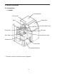
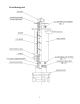
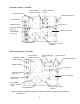
II. General Information A. Construction 1. F-300BAF Ice Storage Bin Bin Control * Spout Sliding Door Control Water Valve Evaporator Reservoir Gear Motor Expansion Valve Compressor Control Box Air-cooled Condenser *The switch actuator is located in the ice storage bin.
B.
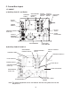
C. Control Box Layout 1.
c) Auxiliary Code L-1 and M-0 GEAR MOTOR PROTECT RELAY CONTROL TIMER WATER CONTROL RELAY PRESSURE SWITCH FLUSH SWITCH POWER SWITCH FLUSH RELAY CONTROL BOARD FUSE (1A) START CAPACITOR GEAR MOTOR FUSE (1.5A) TRANSFORMER CAPACITOR - GEAR MOTOR d) Auxiliary Code M-1 and Later CONTROL TIMER WATER CONTROL RELAY GEAR MOTOR PROTECT RELAY SAFETY RELAY PRESSURE SWITCH FLUSH SWITCH POWER SWITCH FLUSH RELAY CONTROL BOARD FUSE (1A) START CAPACITOR GEAR MOTOR FUSE (1.
D. Timer Board 1. Solid-State Timer Board Control • A HOSHIZAKI exclusive solid-state sequence timer board is employed in Hoshizaki selfcontained flaker icemakers. • All models are pre-tested and factory-adjusted. CAUTION 1. Fragile, handle very carefully. 2. The timer board contains CMOS (Complementary Metal-Oxide Semiconductor) integrated circuits, which are susceptible to failure due to static discharge. It is especially important to use an anti-static wrist strap when handling or replacing the board.
E. Sequence of Operation Hoshizaki utilizes a solid state timer board to switch the components on and off as needed. The sequence is as follows: 1. Startup Flush switch in "ICE" position, power switch in "ON" position. FR energizes. 2. Fill Cycle WV opens and the reservoir fills with water until UF/S closes. Note: GM will not start unless UF/S is closed. For details, see "IV. Service Diagnosis". 3. Ice Purge Cycle (60 seconds) WCR energizes, closing the low water safety circuit and de-energizing WV.
BC open FR de-energized WCR de-energized FWV energized Comp continues FMS continues GM continues GMPR continues 90 seconds GM de-energized GMPR de-energized FWV continues BC closed FR energized WV energized FWV de-energized 6.7 sec. LF/S and UF/S close WCR energized WV de-energized GM energized GMPR energized FR continues 60 seconds Comp energized FMS energized GM continues GMPR continues WCR continues FR continues 5. Compressor and fan motor energize. Ice production begins in 4 to 6 minutes.
III. Technical Information A.
B. Wiring Diagram 1.
2.
3.
4.
C. Sequence of Electrical Circuit 1. Fill Cycle When power switch is moved to "ON" position, water is supplied to reservoir.
2. Ice Purge Cycle When reservoir has filled, gear motor starts.
3. Freeze Cycle Compressor and condenser fan motor start about 60 sec. after gear motor starts.
4. Shutdown Compressor and condenser fan motor stop about 90 sec. after bin control operates, gear motor stops about 60 sec. later. Flush water valve then operates.
5. Cleaning - Flush Switch Compressor and condenser fan motor stop about 90 sec. after manually moving flush switch to FLUSH position. Gear motor stops about 60 sec. later. Flush water valve then operates.
6. Low Water Safety If upper float switch fails to close, water valve remains open until upper float switch closes and water control relay energizes.
7. Spout Safety Switch When saftey switch is activated, the safety switch relay operates, and the icemaker does not run.
8. High Pressure Switch In case of high pressure, pressure switch shuts down unit.
D. Performance Data 1. F-300BAF APPROXIMATE ICE PRODUCTION PER 24 HR. lbs./day (kg/day) APPROXIMATE ELECTRIC CONSUMPTION watts APPROXIMATE WATER CONSUMPTION PER 24 HR. gal./day (l/day) EVAPORATOR OUTLET TEMP. °F (°C) HEAD PRESSURE PSIG (kg/cm²G) SUCTION PRESSURE PSIG ( kg/cm²G ) TOTAL HEAT OF REJECTION Ambient Temp. (°F) 70 80 90 100 70 80 90 100 70 80 90 100 70 80 90 100 70 80 90 100 70 80 90 100 Water Temp.
IV. Service Diagnosis A. Diagnostic Procedure This diagnostic procedure is a sequence check that allows you to diagnose the electrical system and components under normal operating conditions of 70°F or warmer air and 50°F or warmer water temperatures. Before proceeding, check for correct installation, proper voltage per unit nameplate and adequate water supply. 1) Unplug the unit from the electrical outlet and access the control panel. 2) Plug the unit back in.
5) Refill/Low Water Safety Cycle – As ice is produced, the water level in the reservoir drops. As it drops, the upper float switch and lower float switch open. The upper float switch opens first. Nothing occurs at this time. When the lower float switch opens, the refill begins.
B. Diagnostic Charts 1. No Ice Production Problem Possible Cause [1] The icemaker will not a) Power Supply start. (fill cycle, water valve) Remedy 1. Off. 1. Turn on. 2. Power cord unplugged. 2. Plug into receptacle. 3. Loose connection. 3. Tighten. 4. Bad contacts. 4. Check for contintinuity and replace. 5. Blown fuse. 5. Replace. b) Power Switch (Control Box) 1. OFF position. 1. Move to ON position. 2. Bad contacts. 2. Check for continuity and replace. c) High Pressure Switch 1.
Problem Possible Cause j) Water Control Relay 1. Bad contacts. 1. Replace. 2. Open coil. 2. Replace. k) Water Valve 1. Coil winding opened. 1. Replace. l) Shut-off Valve 1. Closed. 1. Open. 2. Water failure. 2. Wait until water is supplied. 1. Disconnected. 1. Connect. 2. Loose terminal. 2. Repair terminal connection. 1. Bad contacts. 1. Check for continuity and replace. 2. Float does not move freely. 2. Clean or replace. 1. Contact fused. 1. Replace.
Problem Possible Cause e) Compressor Remedy 1. Loose connections. 1. Tighten. 2. Motor winding opened 2. Replace. or grounded. f) Power Supply [5] Gear motor and a) Refrigerant Line compressor start, but no ice is produced. 3. Compressor locked and motor protector tripped. 3. Replace compressor. 1. Circuit ampacity too low. 1. Install a larger-sized circuit. 1. Gas leaks. 1. Check for leaks with a leak detector. Replace drier and charge with refrigerant.
Problem [1] Abnormal noise Possible Cause a)Fan Motor b)Compressor Remedy 1. Bearing worn out. 1. Replace. 2. Fan blade deformed. 2. Replace fan blade. 3. Fan blade does not move freely. 3. Replace. 1. Bearings worn out, or 1. Replace. cylinder valve broken. 2. Mounting pad out of position. 2. Reinstall. c) Refrigerant Lines 1. Rub or touch lines or other surfaces. 1. Replace or separate. d)Gear Motor 1. Bearing or gear worn out / damaged. 1. Replace. e)Evaporator 1.
IMPORTANT Ensure all components, fasteners and thumbscrews are securely in place after the equipment is serviced. IMPORTANT 1. The Polyol Ester (POE) oils used in R-404A units can absorb moisture quickly. Therefore it is important to prevent moisture from entering the system when replacing or servicing parts. 2. Always install a new drier every time the sealed refrigeration system is opened. 3. Do not leave the system open for longer than 15 minutes when replacing or servicing parts. A.
the low-side access port with the unit running. 9) Close the two refrigerant access valves, and disconnect the service manifold hoses. 10) Cap the access valves to prevent a possible leak. B. Brazing WARNING 1. Refrigerant R-404A itself is not flammable at atmospheric pressure and temperatures up to 176°F. 2. Refrigerant R-404A itself is not explosive or poisonous.
C. Removal and Replacement of Compressor IMPORTANT Always install a new drier every time the sealed refrigeration system is opened. Do not replace the drier until after all other repair or replacement has been made. Note: When replacing a compressor with a defective winding, be sure to install the new start capacitor and start relay supplied with the replacement compressor.
D. Removal and Replacement of Drier IMPORTANT Always install a new drier every time the sealed refrigeration system is opened. Do not replace the drier until after all other repair or replacement has been made. 1) Unplug the unit from the electrical outlet. 2) Remove the panels. 3) Recover the refrigerant and store it in an approved container. 4) Remove the drier, then place the new drier in position. Install the new drier with the arrow on the drier in the direction of the refrigerant flow.
8) Check for leaks using nitrogen gas (140 PSIG) and soap bubbles. 9) Evacuate the system, and charge it with refrigerant. See the nameplate for the required refrigerant charge. 10) Attach the expansion valve bulb to the suction line in the same location as the previous bulb. The bulb should be at the 12 o'clock position on the tube. Be sure to secure the bulb with the clamp and holder and to insulate it. 11) Place the expansion valve cover in position. 12) Replace the panels in their correct positions.
F. Removal and Replacement of Evaporator Assembly Components CAUTION Make sure that the saftey switch and spout are properly installed after making repairs in the evaporator assembly. Failure to install the safety switch and spout correctly could result in serious damage to the unit.
1. Upper Bearing Wear Check To ensure that the bearing inside the extruding head does not exceed the wear tolerance of .02", follow the instructions below. 1) Unplug the unit from the electrical outlet. 2) Remove the panels. 3) Remove the thumbscrews and take off the spout from the evaporator. .02" Round Stock or Pin Gauge 4) Loosen the cutter with a wrench and remove it. Auger 5) Grasp the top of the auger and move the auger towards you and then try to insert a .
3. Removal and Replacement of Extruding Head 1) Unplug the unit from the electrical outlet. 2) Remove the panels. 3) Remove the thumbscrews and take off the spout from the evaporator. 4) Loosen the cutter with a wrench and remove it. 5) Remove the allen head cap screws and lift off the extruding head. 6) Place new extruding head in place and tighten down allen head cap screws. If the seals on the allen head cap screws are RED, they must be replaced. If the seals are BLUE, they may be re-used.
4) Recover the refrigerant and store it in an approved container. 5) Remove the thumbscrews and take off the spout from the evaporator. 6) Disconnect the water hoses. 7) Remove the allen head cap screws securing the extruding head. Using the cutter, lift out the auger assembly. 8) Remove the insulation and the expansion valve bulb on the suction line. 9) Disconnect the inlet and outlet tubing. 10) Remove the allen head cap screws securing the evaporator to the lower housing. 11) Lift off the evaporator.
7) Remove the allen head cap screws securing the evaporator to the lower bearing housing. 8) Raise the evaporator up to access the lower housing. 9) Remove the O-ring and mechanical seal from the housing. If only replacing mechanical seal, proceed to step 12). WARNING To help prevent water leaks, be careful not to damage the surfaces of the O‑ring or mechanical seal. 6b. Lower Housing 10) Remove the bolts securing the housing to the gear motor and remove the housing from the gear motor.
10) Replace the panels in their correct positions. 11) Plug the unit back in. G. Removal and Replacement of Fan Motor 1) Unplug the unit from the electrical outlet. 2) Remove the panels. 3) Remove the wire connectors from the fan motor leads. 4) Remove the fan motor bracket and fan motor. 5) Install the new fan motor. 6) Replace the fan motor bracket and the wire connectors. 7) Replace the panels in their correct positions. 8) Plug the unit back in. H.
8) Connect the hose to the water valve and secure it with the clamp. 9) Pour water into the reservoir, and check for water leaks. 10) Open the water supply line shut-off valve. 11) Plug the unit back in. 12) Move the flush switch to the "ICE" position. 13) Check for water leaks. 14) Move the flush switch to the "FLUSH" position, and make sure water is flushing. 15) Move the flush switch to the "ICE" position. 16) Replace the panels in their correct positions. 17) Plug the unit back in.
VI. Cleaning and Maintenance IMPORTANT Ensure all components, fasteners and thumbscrews are securely in place after any maintenance or cleaning is done to the equipment. A. Cleaning and Sanitizing Instructions WARNING 1. HOSHIZAKI recommends cleaning this unit at least once a year. More frequent cleaning, however, may be required in some existing water conditions. 2. To prevent injury to individuals and damage to the icemaker, do not use ammonia type cleaners. 3.
Thumbscrews 8) Remove the thumbscrews attaching spout (A) to the evaporator assembly and lift off spout (A) and spout packing (A). See Fig 4. 9) Pour the cleaning solution over the extruding head until the evaporator assembly and the reservoir are filled and the solution starts to overflow into the drain pan. Spout (A) Evaporator Assembly Spout (A) Packing Fig.
4. Sanitizing Procedure - Initial 1) Close the water supply line shut-off valve. 2) In the storage bin, remove the thumbscrews attaching spout (B), then remove spout (B) and spout packing (B). 3) Remove the thumbscrews attaching spout (A) to the evaporator assembly and lift off spout (A) and spout packing (A), and the cylinder packing. 4) Pour the sanitizing solution over the extruding head until the evaporator assembly and the reservoir are filled and the solution starts to overflow into the drain pan.
8) Using the thumbscrews, replace spouts (A) and (B) and spout packings (A) and (B) in their correct positions. 9) Allow the icemaker to sit for about 10 minutes before operation. 10) Move the flush switch to the "ICE" position, then turn on the power supply. Replace the top panel and the front panel in their correct positions. Make ice using the solution until the icemaker stops making ice. 11) Remove the front panel. 12) Move the flush switch to the"FLUSH" position to drain the remainder of the solution.
B. Maintenance IMPORTANT 1. This icemaker must be maintained individually, referring to the instruction manual and labels provided with the icemaker. 2. To have the optimum unit performance, the following parts need periodic inspection and maintenance: Extruding Head and Upper Bearing Housing and Lower Bearing Mechanical Seal Auger Evaporator Cylinder Gear Motor These parts should be inspected at least once a year or every 10,000 hours of operation.
C. Preparing the Icemaker for Long Storage WARNING When shutting off the icemaker for an extended time, drain out all water from the water line and remove the ice from the storage bin. The storage bin should be cleaned and dried. Drain the icemaker to prevent damage to the water supply line at sub-freezing temperatures, using air or carbon dioxide. Shut off the icemaker until the proper ambient temperature is resumed. 1) Run the icemaker with the water supply line shut-off valve closed.