IM SERVICE TRAINING Featuring the IM-51BAE 80041 9/9/99
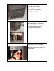
All IM models have similar sequence of operation. This manual is designed as a generic IM Training manual. The Hoshizaki IM series ice machine uses a horizontal evaporator design. This compact unit is designed for counter-top, under-counter, or freestanding installations. A standard 120 volt power cord provides the electrical connection. The unit is designed to operate on a separate 15 amp circuit. The water supply connection is ½”FIP and is located at the bottom right rear of the unit.
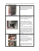
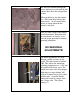
This horizontal evaporator and water distribution system is unique to the IM series. The ABS water plate sprays water up into the evaporator cells to form the square IM cube. The moveable water pan assembly includes the water plate, reservoir pan, and pump motor assembly. Tension springs connect two cam arms to the water plate assembly. An actuator motor rotates the cam arms to raise and lower the water pan during the ice making cycle.
The front cam arm has a switch lever that operates the actuator toggle switch located above the pan assembly. The actuator toggle switch controls the direction of rotation for the actuator motor and energizes the pump motor during the freeze cycle. • When the switch is in the right position, the actuator motor rotates counter clock wise to lower the water pan assembly. • When the switch is in the left position, the actuator motor turns clock wise to raise the water pan assembly.
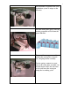
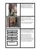
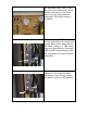
The louver has a flip down cover to access the control switch. The switch has 3 positions. ICE, OFF, & WASH. The louver covers the compressor compartment. Remove the louver screws and lift the louver forward to access the condenser coil fan assembly and compressor. For easy access during preventative maintenance or service, the inlet water valve is located in the front right hand corner of the compressor compartment.
The control box is accessed from the rear of the unit. Remove the screws holding the pipe cover and the control box cover to reach the control board and other components. A solid state board controls the IM operation. Several adjustments are included on the board. These adjustments are factory set for proper operation. Later, we will cover the adjustments and discuss the proper settings. CONTROL SWITCH TO ICE. Now, lets take a look at the basic IM sequence of operation.
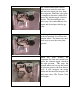
The actuator motor turns counter clock wise to rotate the cam arms and lower the water pan away from the evaporator. When the water plate is completely down the switch lever moves the actuator toggle switch to the left. The board energizes the inlet water valve and condenser fan motor and de-energizes the hot gas valve. Switching the actuator toggle switch to the left position also reverses the actuator motor. The motor now turns clock wise to raise the water plate upward.
The freeze cycle is controlled by a thermistor, which is mounted at the evaporator outlet. The pump is spraying water up into the evaporator cells to form the square IM cubes. The evaporator temperature lowers as the ice cubes form. A thermistor temperature of –9.4°F signals the control board to begin harvest and energize the hot gas valve and actuator motor circuit. The actuator motor now turns counter clock wise to lower the water pan. The switch lever moves the actuator toggle switch to the left.
The unit will continue through the freeze and harvest cycle until the bin control shuts down the refrigeration system. When pushed over, the bin control has a 10-second delay before shut down occurs. An 85-second delay occurs at startup when the bin control is released. Now let’s take a look at the control board adjustments. Remember that the adjustments are factory set to provide proper operation in normal operating conditions.
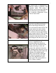
The maximum freeze timer is VR3. This timer will automatically switch the unit to the harvest cycle if the freeze cycle last longer than the setting time. The factory setting is 45 minutes. The defrost control VR2 will adjust the time period between ice-drop and actuator motor restart during harvest. The factory setting is 4. This setting represents approximately 40 seconds. VR2 would be adjusted longer if the unit is operating in a cooler ambient temperature.
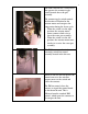
A red Service Indicator LED is also included on the control board. This LED will either light continually or flash to indicate a service fault. A fault diagnosis chart in the service manual will help the technician determine the actual problem. See chart next page. Preventative maintenance for the IM is simple. Follow these steps to allow the unit to operate efficiently. 1. Clean the mesh air filter twice monthly to ensure good airflow. 2. Clean the condenser once a year using a brush or vacuum. 3.
FAULT DIAGNOSIS Check the status of the Service lamp on the Controller Board (LED-5) by removing the Control Box Cover. Lamp ON – Water Plate closed This tends to indicate the Back-up Timer has stopped machine operation during the freeze cycle. High ambient and water temperature are an obvious cause. But check out each component that could result in an extended freezing time (See guide below). Lamp ON – Water Plate open The Timer has stopped the machine because if an excessive defrost time.
PATTERN INTERLOCK INDICATOR WATER TANK POSITION POSSIBLE CAUSE 2 Clogged Air Filter and/or Condenser 1 2 REMEDY Clean or Replace Water leak from Water Solenoid Valve Replace Gas leak from Hot Gas Solenoid Valve Replace 0V Leak Freeze Cycle 3 Hot Gas leak 4 Fan Motor stopped Replace 5 Gas leak Check for leak Gas Compressor stopped 6 3 1 115v Hot Gas Solenoid Valve closed and will not open Gas leak 2 Gas Harvest Cycle 3 4 1 Lever 2 Compressor stopped Actuator Toggle Switc
WIRING DIAGRAM IM-51BAE
IM SERIES REVIEW QUIZ Choose the best answer for each question below. 1. The IM control board is located in the rear or the unit. True False 2. The IM unit uses a thermostatic bin control. True False 3. The bin control switch must OPEN or Close to shut the unit down. 4. The IM series uses R-404A or R-134A refrigerant. 5. To raise the water pan assembly the actuator toggle switch must be in the RIGHT or LEFT position. 6.
NOTES: Quiz answers: 1.True, 2. False, 3. Close, 4. R-134A , 5. Left , 6. CW , 7. – 9.4ºF, 8. 45 min., 9. Harvest initiation, 10.