
Service Manual


Table Of Contents
- Important Safety Information
- I. Construction and Water/Refrigeration Circuit Diagram
- A. Construction
- B. Icemaking Unit
- C. Water/Refrigeration Circuit Diagram
- II. Sequence of Operation and Service Diagnosis
- A. Sequence of Operation Flow Chart
- 1. Icemaking and Drain Cycle
- 2. Shutdown
- B. Service Diagnosis
- 1. Ice Production Check
- 2. Diagnostic Procedure
- C. Control Board Check
- D. Bin Control Check
- E. Float Switch Check and Cleaning
- F. Diagnostic Tables
- III. Controls and Adjustments
- A. Control Board
- B. Controls and Adjustments
- 1. Default Dip Switch Settings
- 2. Infrared Sensor Shutdown Delay (S1 dip switch 1, 2, 3).
- 3. Drain Frequency Control (S1 dip switch 4)
- 4. Continuous Dispensing Timer (S1 dip switch 5 & 6)
- 5. Bin Control Selector (S1 dip switch 7)
- 6. Agitation and Ice Purge Timer (S1 dip switch 8)
- 7. Mechanical Shutdown Delay (S1 dip switch 9)
- 8. Factory Use (S1 Dip Switch 10)
- C. Power Switch and Control Switch
- IV. Refrigeration Circuit and Component Service Information
- A. Refrigeration Circuit Service Information
- B. Component Service Information
- V. Maintenance
- VI. Disposal
- VII. Technical Information
- A. Specification & Performance Data Sheets
- 1. F-300BAJ
- 2. F-500BAJ
- B. Wiring Diagrams
- 1. F-300BAJ
- 2. F-500BAJ
50
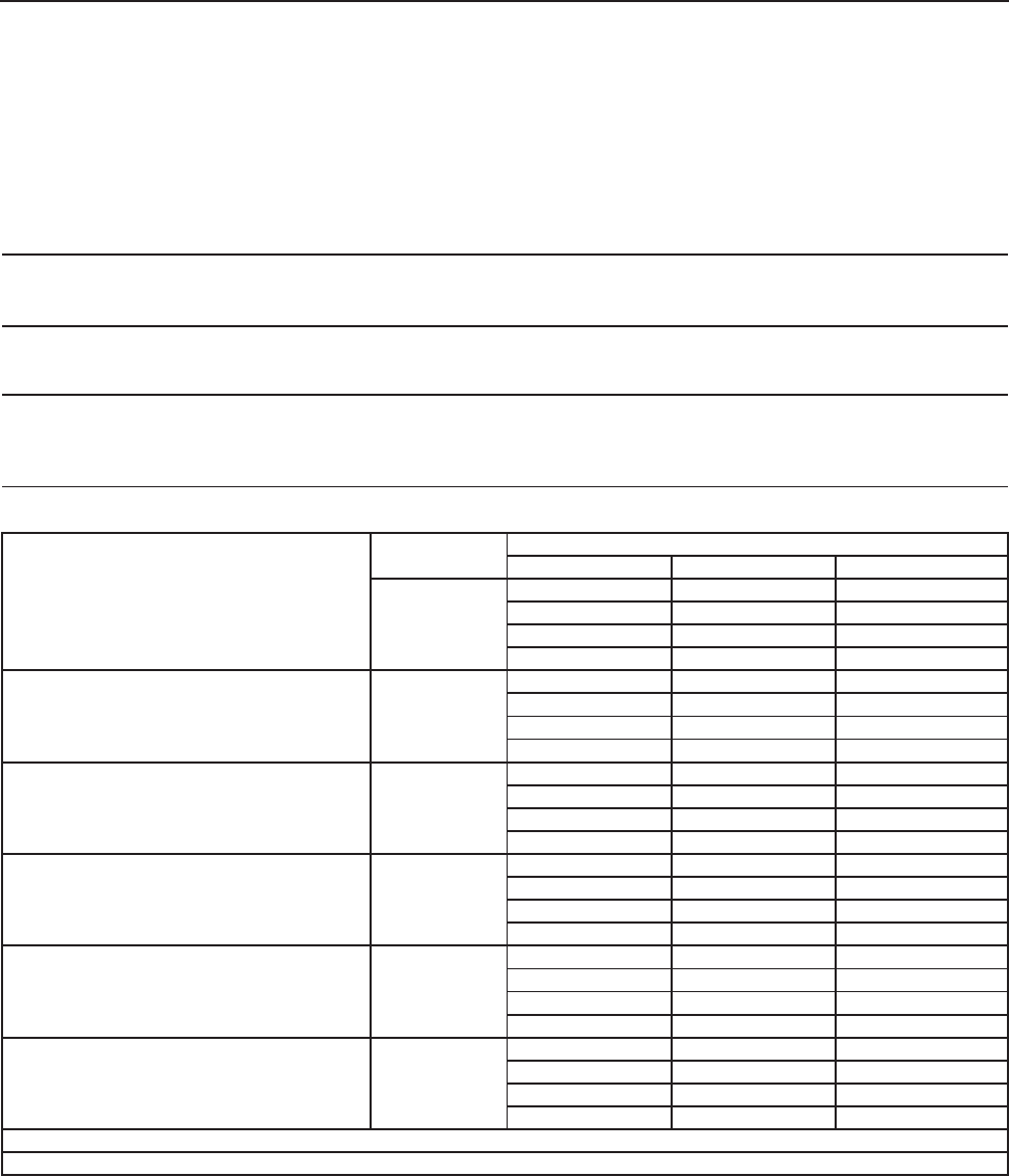
VII. Technical Information
We reserve the right to make changes in specications and design without prior notice.
A. Specication & Performance Data Sheets
Note: The data in bold should be used for reference.
1. F-300BAJ
Specification Sheet
AC SUPPLY VOLTAGE 115/60/1
AMPERES 7.8 AMPS (AT 104°F / WT 80°F)
MAX. HACR BREAKER SIZE 15 AMPS
ELECTRIC & WATER CONSUMPTION 90/70°F 70/50°F
ELECTRIC W (kWH/100 lbs.) 627(6.14) 586(3.97)
POTABLE WATER 30(12.0) 42(12.0)
SHAPE OF ICE Flake
ICE HARDNESS 72% @ (32/21 (90/70), Conductivity 200 µs/cm)
BIN CONTROL SYSTEM Mechanical Bin Control ( Proximity Sw. )
REFRIGERANT CHARGE R404A, 0 lb. 9.2 oz. (260g)
Performance Data Sheet
APPROXIMATE Ambient
ICE PRODUCTION Tem
p
. °F
(
°C
)
PER 24 HR.
70 (21)
353
(
160
)
342
(
155
)
323
(
147
)
80 (26)
305
(
139
)
289
(
131
)
273
(
124
)
90 (32)
258
(
117
)
247
(
112
)
230
(
104
)
lbs./da
y (
k
g
/da
y)
100 (38)
217
(
99
)
205
(
93
)
188
(
85
)
APPROXIMATE ELECTRIC
70 (21)
586 -
-
592 -
-
598 -
-
CONSUMPTION
80 (26)
604 -
-
610 -
-
616 -
-
90 (32)
621 -
-
627 -
-
646 -
-
watts
100 (38)
665 -
-
683 -
-
702 -
-
APPROXIMATE WATER
70 (21)
42
(
160
)
41
(
156
)
39
(
147
)
CONSUMPTION PER 24 HR.
80 (26)
37
(
139
)
35
(
131
)
33
(
124
)
(
TOTAL
)
90 (32)
31
(
117
)
30
(
112
)
28
(
104
)
g
al. / da
y (
l/da
y)
100 (38)
26
(
99
)
25
(
93
)
23
(
85
)
EVAPORATOR OUTLET TEMP.
70 (21)
24
(
(
-4
)
)
25
(
(
-4
)
)
25
(
(
-4
)
)
°F
(
°C
)
80 (26)
26
(
(
-3
)
)
26
(
(
-3
)
)
27
(
(
-3
)
)
90 (32)
27
(
(
-3
)
)
28
(
(
-2
)
)
28
(
(
-2
)
)
100 (38)
28
(
(
-2
)
)
28
(
(
-2
)
)
28
(
(
-2
)
)
HEAD PRESSURE
70 (21)
243
(
17.1
)
253
(
17.8
)
263
(
18.5
)
80 (26)
273
(
19.2
)
283
(
19.9
)
293
(
20.6
)
90 (32)
303
(
21.3
)
313
(
22.0
)
323
(
22.7
)
PSIG
(
k
g
/cm
2
G
)
100 (38)
332
(
23.3
)
342
(
24.0
)
351
(
24.7
)
SUCTION PRESSURE
70 (21)
38
(
2.6
)
39
(
2.7
)
40
(
2.8
)
PSIG
(
k
g
/cm
2
G
)
80 (26)
40
(
2.8
)
41
(
2.9
)
42
(
3.0
)
90 (32)
43
(
3.0
)
44
(
3.1
)
44
(
3.1
)
100 (38)
45
(
3.1
)
45
(
3.1
)
45
(
3.2
)
BTU/h
(
AT 90°F / WT 70°F
)
BTU/h
(
AT 90°F / WT 70°F
)
HEAT OF REJECTION FROM CONDENSER 2,300
HEAT OF REJECTION FROM COMPRESSOR 700
Water Temp. °F (°C)
50 (10) 70 (21) 90 (32)
ENG F-013.0.1196