
Service Manual


Table Of Contents
- Important Safety Information
- I. Construction and Water/Refrigeration Circuit Diagram
- A. Construction
- B. Icemaking Unit
- C. Water/Refrigeration Circuit Diagram
- II. Sequence of Operation and Service Diagnosis
- A. Sequence of Operation Flow Chart
- 1. Icemaking and Drain Cycle
- 2. Shutdown
- B. Service Diagnosis
- 1. Ice Production Check
- 2. Diagnostic Procedure
- C. Control Board Check
- D. Bin Control Check
- E. Float Switch Check and Cleaning
- F. Diagnostic Tables
- III. Controls and Adjustments
- A. Control Board
- B. Controls and Adjustments
- 1. Default Dip Switch Settings
- 2. Infrared Sensor Shutdown Delay (S1 dip switch 1, 2, 3).
- 3. Drain Frequency Control (S1 dip switch 4)
- 4. Continuous Dispensing Timer (S1 dip switch 5 & 6)
- 5. Bin Control Selector (S1 dip switch 7)
- 6. Agitation and Ice Purge Timer (S1 dip switch 8)
- 7. Mechanical Shutdown Delay (S1 dip switch 9)
- 8. Factory Use (S1 Dip Switch 10)
- C. Power Switch and Control Switch
- IV. Refrigeration Circuit and Component Service Information
- A. Refrigeration Circuit Service Information
- B. Component Service Information
- V. Maintenance
- VI. Disposal
- VII. Technical Information
- A. Specification & Performance Data Sheets
- 1. F-300BAJ
- 2. F-500BAJ
- B. Wiring Diagrams
- 1. F-300BAJ
- 2. F-500BAJ
32
B. Controls and Adjustments
NOTICE
Dip switches are factory set. Failure to maintain factory settings may adversely
affect performance and warranty coverage. For more information, contact your
Hoshizaki Certied Service Representative.
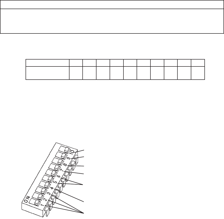
1. Default Dip Switch Settings
The S1 dip switch settings are factory-set to the following positions:
Dip Switch No. 1 2 3 4 5 6 7 8 9 10
F-300BAJ
F-500BAJ
OFF OFF OFF OFF OFF OFF OFF ON OFF OFF
infrared sensor Shutdown Delay
Continuous Dispensing Timer
(DCM models only, do not adjust on modular icemakers)
Drain Frequency Control
Bin Control Selector
Mechanical Shutdown Delay
Normally off (factory use)
Periodic Agitation (DCM-270 only) and Ice Purge Timer