
Service Manual


Table Of Contents
- Important Safety Information
- I. Construction and Water/Refrigeration Circuit Diagram
- A. Construction
- B. Icemaking Unit
- C. Water/Refrigeration Circuit Diagram
- II. Sequence of Operation and Service Diagnosis
- A. Sequence of Operation Flow Chart
- 1. Icemaking and Drain Cycle
- 2. Shutdown
- B. Service Diagnosis
- 1. Ice Production Check
- 2. Diagnostic Procedure
- C. Control Board Check
- D. Bin Control Check
- E. Float Switch Check and Cleaning
- F. Diagnostic Tables
- III. Controls and Adjustments
- A. Control Board
- B. Controls and Adjustments
- 1. Default Dip Switch Settings
- 2. Infrared Sensor Shutdown Delay (S1 dip switch 1, 2, 3).
- 3. Drain Frequency Control (S1 dip switch 4)
- 4. Continuous Dispensing Timer (S1 dip switch 5 & 6)
- 5. Bin Control Selector (S1 dip switch 7)
- 6. Agitation and Ice Purge Timer (S1 dip switch 8)
- 7. Mechanical Shutdown Delay (S1 dip switch 9)
- 8. Factory Use (S1 Dip Switch 10)
- C. Power Switch and Control Switch
- IV. Refrigeration Circuit and Component Service Information
- A. Refrigeration Circuit Service Information
- B. Component Service Information
- V. Maintenance
- VI. Disposal
- VII. Technical Information
- A. Specification & Performance Data Sheets
- 1. F-300BAJ
- 2. F-500BAJ
- B. Wiring Diagrams
- 1. F-300BAJ
- 2. F-500BAJ
23
D. Bin Control Check
Bin Control Check
When the actuator paddle is not engaged BC is closed and the icemaker produces ice.
With CB S1 dip switch 7 placed in the "OFF" position, BC is used as a stand-alone bin
control. The stand-alone application should only be used in standard ice storage bin
applications. When ice lls the chute and engages the actuator paddle, BC opens and
CB starts the 150-sec. shutdown sequence.
1) Remove the front panel and move the power switch to the "OFF" position, then unplug
the appliance from the electrical outlet (F-300BAJ) or turn the power supply off
(F-500BAJ).
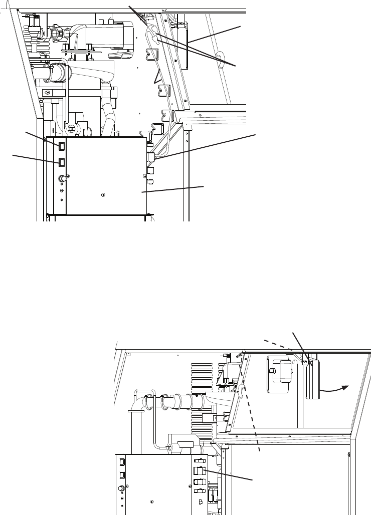
2) Disconnect the 12 pin connector from the control box or disconnect the bell connectors.
See Fig. 2.
Fig. 2
Fig. 3
3) Open the ice storage bin door so that you can access the actuator paddle located in the
top of the bin. See Fig. 3.
4) With actuator paddle not engaged, check for continuity across BC GY wires (proximity
switch) in 12 pin connector plug or black (BK) wires from bell connectors. BC closed.
If BC continuity indicates open BC with the actuator paddle engaged, replace BC
(proximity switch).
5) Press the actuator paddle located
in the top of the bin to the right
(actuator paddle engaged). Check
for continuity across BC GY
wires (proximity switch) in 12 pin
connector plug or black (BK) wires
from bell connectors. BC open.
IfBC continuity indicates closed BC
with the actuator paddle engaged,
replace BC (proximity switch).
Actuator Paddle
Bell Connectors
12 Pin Connector
Control Box
Control Switch
Powerl Switch
12 Pin Connector
Actuator Paddle
Bell Connectors
Proximity Switch
GY Wire
BK Wire
Model Shown: F-300BAJ
Model Shown: F-300BAJ